edwina@edwin-pump.com

View All Products
en
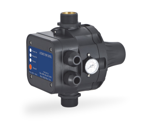
Modern water pump systems require more than a motor and a hydraulic connection. They need dependable control components that can monitor pressure, respond at the correct operating point, protect the pump from unnecessary cycling, and support stable water delivery. The EPC-10 Series Manual and Time Modes NBR Rubber Membrane Pressure Switches are designed for this purpose. They provide a practical control solution for domestic water systems, booster installations, irrigation equipment, general water supply systems, and other applications in which accurate pressure management is essential.
The EPC-10 Series combines pressure-switch functionality with manual and time-based operating modes. This arrangement gives installers and operators greater flexibility than a basic pressure switch that only reacts to a fixed pressure condition. The product supports adjustable starting pressure, adjustable stopping pressure, and delay-start settings. It also uses an NBR rubber membrane to create a reliable separation between the water circuit and the electrical switching mechanism.
With a starting pressure setting from 0.5 bar to 6.7 bar, a stopping pressure setting from 0.8 bar to 7.0 bar, a maximum working pressure of 1.0 MPa, and an IP65 protection rating, the EPC-10 Series is suitable for a broad range of water pump systems. Its maximum working temperature of 60°C further supports use in demanding indoor and outdoor installations where the control unit may be exposed to elevated ambient conditions.
This article examines the design, operating principles, technical characteristics, application value, installation considerations, and manufacturing strengths associated with the EPC-10 Series. It also explains why a pressure switch with flexible operating modes, a durable membrane, carefully controlled production, and export-oriented quality management can provide meaningful advantages over simpler control devices.
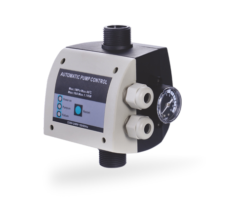
EPC-10 Series Manual and Time Modes NBR Rubber Membrane Pressure Switches for Usage with Water Pump System
A pressure switch is an essential control component in many water pump installations. Its main function is to detect pressure in the connected water system and use that pressure condition to control an electrical circuit. Depending on the configuration, the switch can start a pump when system pressure falls below a selected threshold and stop the pump when pressure rises to a defined upper threshold.
The EPC-10 Series is developed specifically for water pump systems. Instead of treating pressure control as a single fixed action, it provides adjustable settings for both starting and stopping. This allows the installer to match the control response to the pump’s hydraulic performance, the size of the pressure tank, the expected water demand, and the requirements of the end user.
The product also supports manual and time modes. Manual operation can be valuable during commissioning, maintenance, troubleshooting, or temporary operation. Time-based control can help introduce a delay before startup, reducing the possibility of immediate repeated activation when pressure fluctuates briefly. This flexibility makes the product useful in systems that experience changing demand patterns or intermittent pressure conditions.
In a residential booster system, for example, the switch can be adjusted to start the pump when water pressure drops as taps or showers are opened. It can then stop the pump after the pressure reaches the selected upper setting. In an irrigation or utility installation, the time-delay function may help coordinate pump operation with valves, controls, or expected demand cycles.
The EPC-10 Series is not simply an electrical accessory. It is an interface between the hydraulic system and the pump motor. Its performance affects energy use, equipment service life, water pressure stability, and the overall convenience of operating the system.
The product is available with a rated voltage of 110V–120V and operates at 50/60Hz. This electrical specification makes it suitable for compatible power systems in markets using these voltage and frequency conditions. The unit must always be matched with the actual motor rating, electrical supply, and installation requirements of the pump system.
The adjustable starting pressure range is 0.5–6.7 bar, while the adjustable stopping pressure range is 0.8–7.0 bar. These ranges provide considerable freedom for configuring a low-pressure household system, a domestic booster unit, or a more demanding water supply installation within the product’s rated limits.
The delay-start setting is available from 0.1 to 1 hour and from 1 to 24 hours. This broad setting range allows the installer to configure either a short delay for pressure stabilization or a longer scheduled interval where the application requires time-based operation. The correct setting depends on the pump, water demand, pipe volume, control strategy, and system safety requirements.
The maximum working pressure is 1.0 MPa, equivalent to approximately 10 bar. The maximum working temperature is 60°C, and the stated protection rating is IP65. IP65 indicates protection against dust ingress and water jets from limited directions when the enclosure is correctly installed and sealed. It does not mean that the controller should be submerged or exposed to unrestricted high-pressure water.
The available connection configurations include female and male screw types. The listed screw sizes include a 1/4-inch connection, with a fixed nut option of 1/4 inch or 3/8 inch and a rotary connection option of 1/4 inch. Before ordering or installation, the connection arrangement should be checked against the pump outlet, manifold, pressure tank, pipework, and any required adapters.
Parameter | Specification | Application Significance |
Product series | EPC-10 | Pressure control for water pump systems |
Rated voltage | 110V–120V | For compatible electrical supply systems |
Frequency | 50/60Hz | Supports common power frequencies |
Starting pressure | 0.5–6.7 bar | Adjustable pump activation threshold |
Stopping pressure | 0.8–7.0 bar | Adjustable pump deactivation threshold |
Delay-start setting | 0.1–1 hour and 1–24 hours | Supports delayed or scheduled activation |
Maximum working pressure | 1.0 MPa | Defines the maximum rated hydraulic pressure |
Membrane material | NBR rubber | Provides flexible hydraulic sensing and sealing |
Protection rating | IP65 | Improves resistance to dust and water jets |
Maximum working temperature | 60°C | Supports moderately elevated ambient conditions |
Connection type | Male or female options | Allows adaptation to different system layouts |
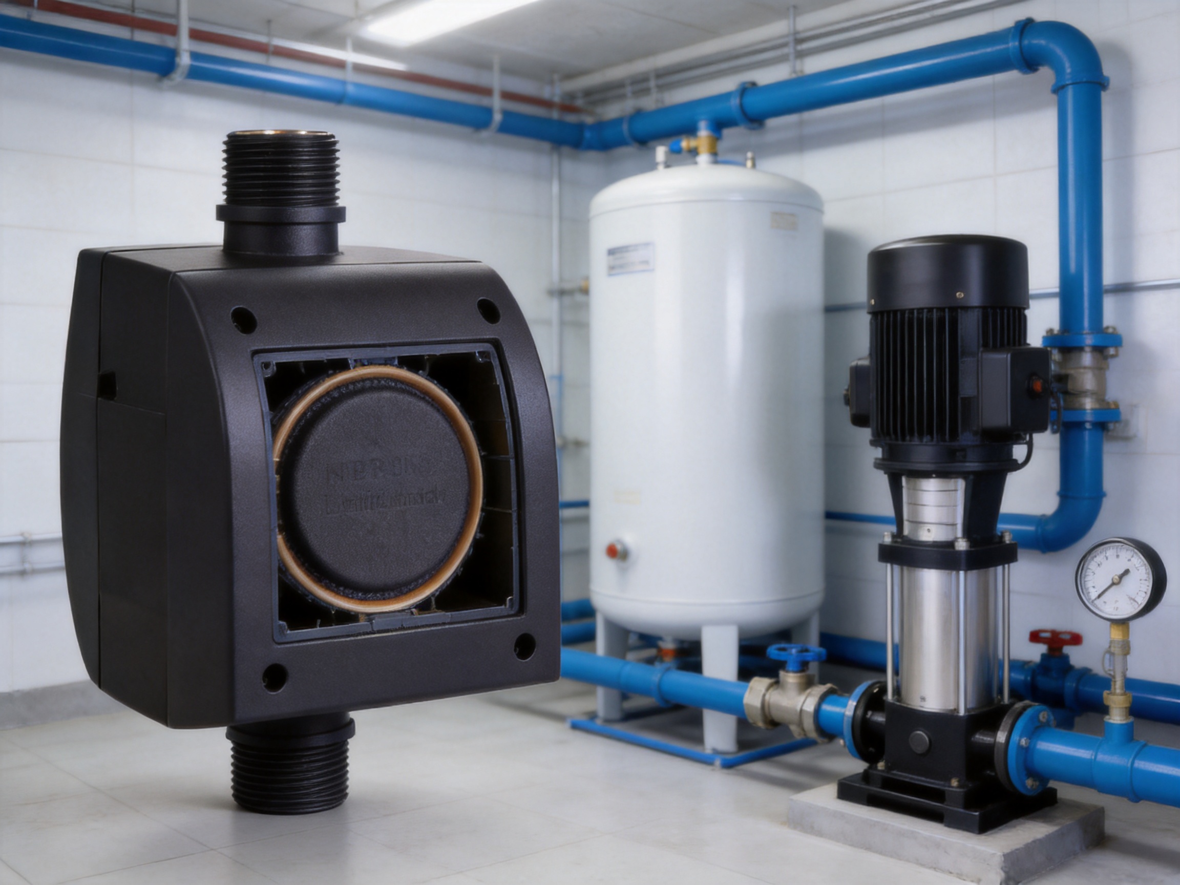
The membrane is one of the most important elements in a mechanical pressure switch. It transfers hydraulic pressure into a mechanical movement that operates the electrical contacts. At the same time, it helps isolate the water or fluid from the electrical section of the device. The choice of membrane material therefore affects sealing, sensitivity, durability, and compatibility.
The EPC-10 Series uses NBR, also known as nitrile butadiene rubber. NBR is widely used in water-related mechanical components because it provides good resistance to many oils, greases, and common industrial fluids while also offering useful elasticity and sealing performance. In a pressure switch, its flexibility allows the membrane to respond to pressure changes without requiring a complicated sensing structure.
A well-designed NBR membrane can help reduce the risk of leakage around the sensing chamber. It can also contribute to consistent pressure response when the switch is correctly installed and used within its rated limits. The membrane must withstand repeated deflection as the pump starts and stops, which makes material consistency and molding quality important aspects of product reliability.
The membrane should not be considered a universal solution for every chemical or high-temperature fluid. The EPC-10 Series is intended for water pump systems, and users should confirm fluid compatibility before applying it to treated water, aggressive chemicals, hydrocarbons, or fluids containing unusual additives. For standard water applications, the NBR material offers a practical balance between cost, flexibility, and sealing capability.
Compared with a basic control unit using an inferior or poorly formed diaphragm, a pressure switch with a properly manufactured NBR membrane can offer more reliable separation between the hydraulic and electrical areas. It can also help maintain more stable operation over repeated pressure cycles. These benefits are particularly valuable in booster systems that operate frequently throughout the day.
Manual mode allows the operator or installer to exercise direct control over the pump system during selected situations. This can be useful when filling a pipeline, testing the pump, checking a pressure tank, flushing a system, or diagnosing a suspected fault. Manual operation can also provide a temporary alternative when water demand must be maintained while the automatic pressure settings are being reviewed.
Manual control should be used responsibly. A pump must not be allowed to run without sufficient water, and the installer should verify that the motor, pipework, valves, and pressure vessel can safely tolerate the operating condition. Manual mode is a convenience and commissioning feature; it does not replace appropriate dry-run protection, overload protection, relief devices, or other safety equipment where those devices are required.
Time mode provides another layer of flexibility. The EPC-10 Series includes delay-start settings from short intervals of 0.1–1 hour and longer intervals of 1–24 hours. The exact use of this function depends on the system design. A short delay may help prevent immediate pump activation caused by a temporary pressure fluctuation. A longer interval may support scheduled water delivery or a controlled operating routine.
Time-based operation can be particularly helpful in systems with changing water demand. Agricultural irrigation, tank filling, process support, and certain building services may not require the pump to respond instantly to every small pressure variation. A delay can reduce unnecessary starts and allow the system to settle before the motor is energized.
However, a delay should not be set without considering user comfort and system needs. Excessive delay may cause insufficient pressure at the point of use. An unsuitable delay may also cause a pump to remain inactive when water is urgently required. The appropriate setting should be selected through commissioning tests under realistic demand conditions.
The product description identifies two possible control modes: normally open and normally closed. In the normally open arrangement, the switch remains open below the selected pressure point and closes when pressure reaches the relevant set point. In the normally closed arrangement, the switch remains closed below the selected pressure point and opens when pressure reaches the set point.
These configurations provide flexibility when integrating the pressure switch with different control circuits. The correct contact arrangement depends on whether the switch is being used to energize a relay, interrupt a motor circuit, provide a signal to a controller, or work with a particular pump-control architecture.
Because electrical systems vary, the contact logic should be verified before wiring. The power supply must be isolated during installation, and connections should be completed by a qualified professional. The pressure switch should not be connected directly to a motor unless the switch’s electrical rating is suitable for the motor’s starting and running current. In many installations, a relay, contactor, or additional motor-protection device is appropriate.
The EPC-10 Series offers several practical advantages over a simple, single-setting pressure switch. The first is adjustment range. With separate starting and stopping pressure settings, the installer can create a control differential that better matches the pump and water network. This can help prevent rapid cycling, which occurs when a pump starts and stops repeatedly over a short period.
The second advantage is mode flexibility. Basic pressure switches often provide only one automatic response. The manual and time modes of the EPC-10 Series allow the same device to support commissioning, regular operation, temporary control, and delayed activation. This can reduce the need for separate accessories in certain system designs.
The third advantage is the use of an NBR rubber membrane. A membrane-based hydraulic sensing arrangement provides physical separation between the fluid circuit and the electrical contact section. It also offers a simple and familiar mechanical principle that can be serviced and understood by pump installers around the world.
The fourth advantage is environmental protection. The IP65 enclosure rating improves resistance to dust and water jets compared with unprotected electrical components. This is important in pump rooms, utility areas, agricultural environments, workshops, and outdoor cabinets where splashing or airborne dust may occur.
The fifth advantage is connection flexibility. Male and female versions and several 1/4-inch and 3/8-inch connection arrangements make it easier to integrate the unit into different manifolds and pipe layouts. Connection flexibility can reduce installation modifications and support replacement of older control devices, provided that the hydraulic and electrical ratings are correctly matched.
These advantages do not mean that every pressure switch is suitable for every pump. The EPC-10 Series must still be selected according to voltage, current, pressure, temperature, fluid, connection dimensions, pump output, and local regulations. Its value comes from combining multiple useful functions in a compact control component intended for water systems.
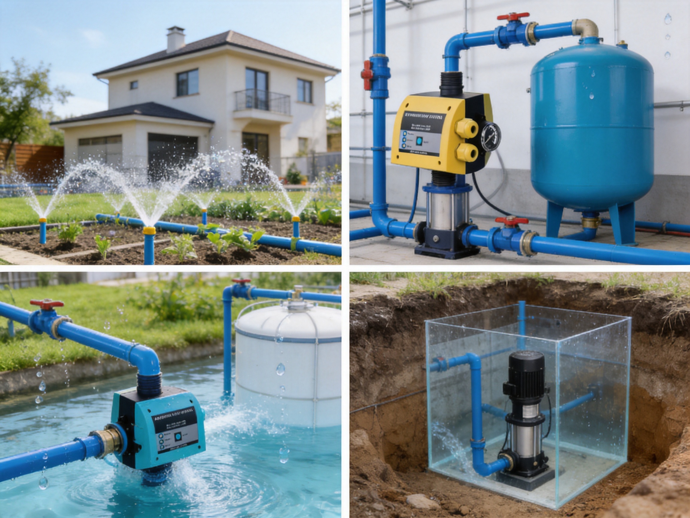
In residential buildings, pressure may be insufficient because of elevation, long pipe runs, municipal supply limitations, or high simultaneous demand. A booster pump can increase water pressure, while the EPC-10 Series can control pump activation and stopping according to actual system pressure.
The adjustable starting pressure makes it possible to select a response suitable for showers, faucets, washing equipment, and other household fixtures. The stopping pressure can be set high enough to provide useful pressure without exceeding the safe rating of the piping and connected equipment. Proper adjustment helps maintain comfortable water delivery while reducing unnecessary pump operation.
Garden pumps and irrigation systems often experience intermittent demand. Valves may open and close at different times, and the water requirement can change according to the season, crop, weather, or watering schedule. A pressure switch with time-control capability can support more organized operation in these conditions.
The installer can configure pressure thresholds according to the pump’s discharge characteristics and the required sprinkler or drip-irrigation pressure. A suitable delay may help prevent the pump from reacting to short pressure fluctuations caused by valve movement or pipe filling. For outdoor installations, the IP65 rating offers useful protection when the controller is placed in an appropriately sheltered and correctly sealed location.
Surface pumps are commonly used for water transfer, household supply, irrigation, rainwater utilization, and general utility applications. Their suction and discharge conditions can vary significantly. The EPC-10 Series can be installed as part of a pressure-control assembly when the hydraulic conditions fall within the switch’s rated limits.
Special attention should be given to priming, suction lift, inlet filtration, and protection against dry running. A pressure switch cannot compensate for a blocked suction line, inadequate water level, air leakage, or insufficient pump capacity. The best results are achieved when the pressure switch is used as one part of a complete and correctly engineered pump system.
Submersible and deep-well pumps can supply water from wells, underground storage, boreholes, and tanks. In these applications, the EPC-10 Series may be used in the discharge-side control system, provided that the pump motor and control panel are compatible with the switch.
Deep-well installations require careful attention to static water level, drawdown, pipe friction, check valves, pressure tanks, and motor protection. The pressure switch should normally control a suitable contactor or dedicated pump controller rather than carrying a motor load beyond its rating. The set points should be selected so that the pump can build pressure reliably without operating against an unsuitable deadhead condition.
Some water circulation and utility systems require pressure-based activation or coordination with other equipment. While pressure switching is not appropriate for every circulation pump, the EPC-10 Series may be considered where system pressure is a suitable indicator of demand and where the operating temperature and fluid conditions remain within specification.
Heating, cooling, and process applications require additional evaluation because fluid temperature, chemical treatment, and material compatibility may differ from ordinary water supply conditions. The stated maximum working temperature is 60°C, and the NBR membrane should be verified for the intended fluid before use.
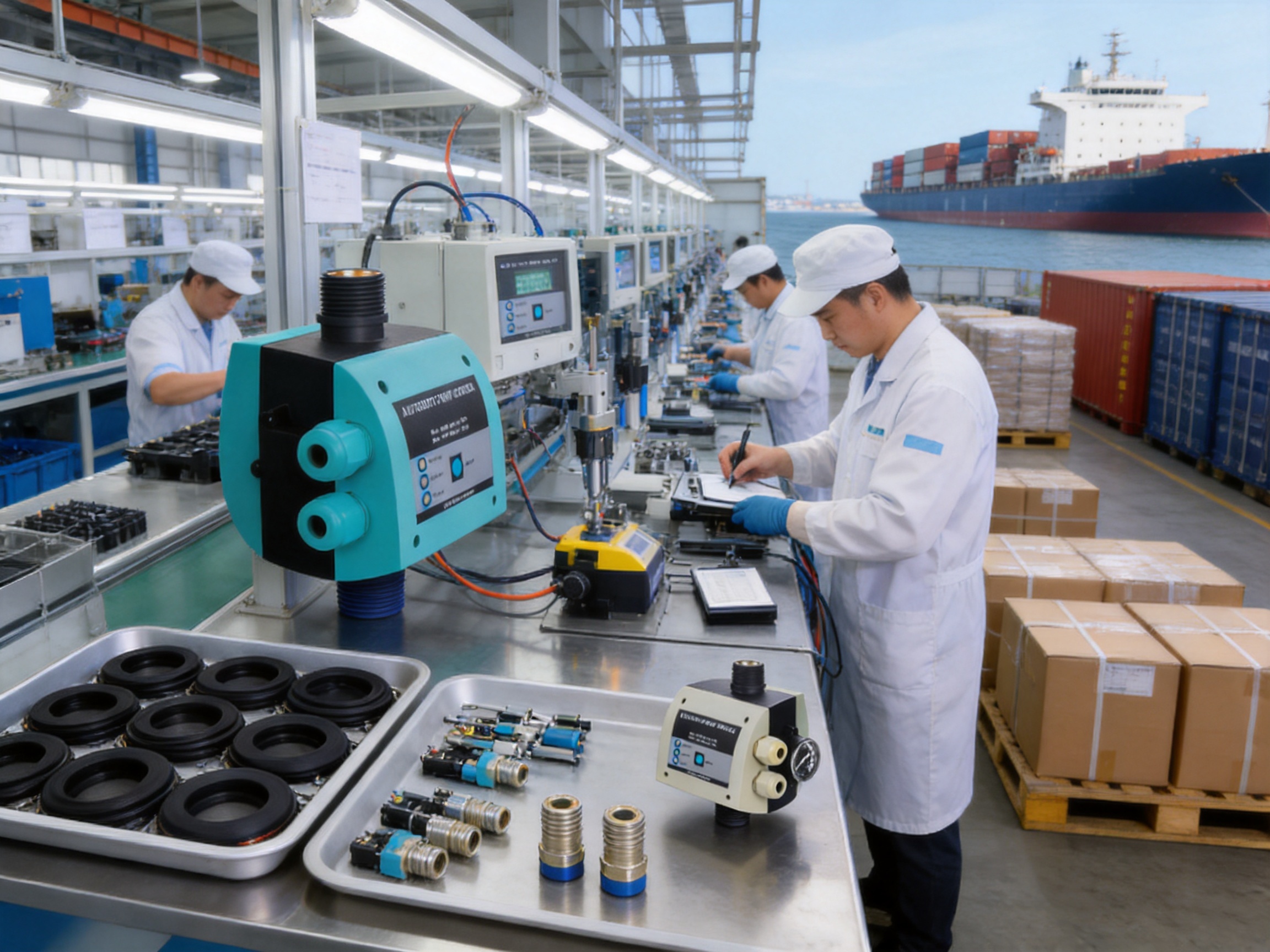
The EPC-10 Series is produced by Taizhou Edwin Electric Co., Ltd., an integrated manufacturing enterprise established in 2008. The company’s reported activities include independent research and development, mass production, and global export. This combination is important for pressure-control products because consistent performance depends not only on the design concept but also on repeatable manufacturing, inspection, assembly, and after-sales support.
Independent research and development allows a manufacturer to adapt product structures to actual market requirements. For a pressure switch, this may include the selection of membrane materials, contact arrangements, adjustment mechanisms, housing design, connection formats, sealing details, and control functions. A company with internal technical capability can improve these elements without relying entirely on external designs.
Mass production also provides a practical advantage. Pressure switches contain small mechanical and electrical components that must work together accurately. Stable production processes can help control dimensional tolerances, contact alignment, membrane installation, screw accuracy, enclosure assembly, and final switching performance. When these processes are standardized, customers can expect more consistent behavior from batch to batch.
The company’s wider product portfolio includes deep-well pumps, submersible pumps, domestic booster pumps, circulation pumps, solar water pumps, intelligent booster pumps, and related water-treatment peripheral products. This product breadth gives the manufacturer direct exposure to different pump operating conditions. Such experience can support more application-oriented development of pump accessories and control components.
In addition to manufacturing, the company has developed affiliated import and export organizations to support procurement planning, order tracking, cross-border delivery, and foreign-trade services. For international buyers, this can simplify communication and support the coordination of product selection, packaging, documentation, production schedules, and shipment arrangements.
A reliable pressure switch begins with appropriate raw materials and components. The NBR membrane must have consistent elasticity, thickness, and molding quality. The enclosure must provide the required protection against dust and water exposure. Electrical contacts must be suitable for the intended switching conditions, and terminals must be securely fixed to reduce the risk of loose connections.
Material control should include incoming inspection, supplier evaluation, batch identification, and traceability where required. For a manufacturer serving global industrial customers, consistent material sourcing is particularly important because pressure switches may be installed in different climates, pump rooms, agricultural environments, and commercial facilities.
Mechanical assembly quality affects the pressure response of the product. The membrane must be correctly seated, fasteners must be tightened consistently, and the pressure-adjustment mechanism must move smoothly. Incorrect assembly can create leakage, unstable switching, poor repeatability, or a pressure range that does not match the intended specification.
Controlled assembly procedures help reduce these risks. Work instructions, fixture-assisted positioning, torque control, visual inspection, and operator training are all useful tools. The objective is to ensure that each unit has the same basic mechanical relationship between the sensing membrane, spring or adjustment mechanism, contact system, and housing.
Electrical testing is essential because the pressure switch forms part of a pump motor control circuit. Testing may include terminal continuity, contact switching, insulation condition, connection security, and operation under representative voltage and frequency conditions. The product’s 110V–120V rating and 50/60Hz frequency specification must be reflected in the inspection and labeling process.
Where the switch is used with a contactor or relay, the electrical interface must be checked for correct operation. The contact state should correspond to the selected normally open or normally closed configuration. Clear terminal marking and consistent documentation can reduce wiring errors during installation.
Hydraulic testing is another important part of manufacturing quality. A pressure switch should be evaluated for leakage, pressure response, adjustment range, and stability within its rated operating conditions. Testing the hydraulic chamber helps verify that the NBR membrane and sealing interfaces perform as intended.
Pressure testing should be performed with calibrated equipment and documented procedures. The test pressure, holding time, switching points, and acceptance criteria should be appropriate to the product design. Consistent testing supports customer confidence and helps identify defects before products leave the factory.
The IP65 rating requires attention to enclosure design, cover fit, seals, cable or terminal entry points, and assembly procedures. A protective rating can be compromised if a cover is not closed correctly, a gasket is damaged, or an unsuitable cable entry is used during installation. Factory inspection should therefore verify both the enclosure components and the completed assembly.
Final inspection may include visual checks, label verification, connection inspection, pressure adjustment checks, functional testing, and packaging review. These steps are especially valuable for export products because the unit may travel long distances and pass through several handling stages before reaching the end user.
The manufacturer has invested in new-energy and intelligent technology since 2018, including solar water pumps and intelligent booster pumps. This development direction indicates experience with more advanced water-management systems in which pump operation, energy efficiency, automation, and remote or intelligent control may work together.
Although the EPC-10 Series is a pressure switch rather than a complete smart pump controller, its adjustable modes and pressure settings fit within the broader trend toward more flexible pump automation. A pressure-control accessory must be reliable enough to work as part of a larger system that may include sensors, inverters, pressure tanks, valves, and intelligent control panels.
The company serves applications including new-energy projects, agricultural irrigation, municipal engineering, mining, construction, heating and ventilation systems, and household water supply. These sectors place different demands on water equipment. Agricultural systems may prioritize ruggedness and simple maintenance, while commercial or municipal projects may require documentation, repeatability, and organized supply. Experience across multiple sectors can strengthen a manufacturer’s understanding of application variation.
For global customers, manufacturing strength includes more than production capacity. It also includes product communication, order organization, packaging, export documentation, delivery coordination, and responsiveness to technical questions. A one-stop procurement approach can be useful when buyers need pumps, pressure switches, valves, pipes, and other related components for a complete project.
Compared with suppliers that only trade standard components, an integrated manufacturer can often provide more direct communication between engineering, production, quality control, and sales teams. This may help with product customization, packaging requirements, connection arrangements, private labeling, order quantities, and project-specific technical discussions, subject to factory capability and agreement.
The EPC-10 Series should be installed by a qualified technician familiar with water pump systems and electrical safety. Before installation, isolate the electrical supply, close relevant water valves, release pressure from the system, and confirm that the pipe connection and electrical rating are compatible with the product.
The pressure switch should be installed in a location where the pressure being measured accurately represents the pressure in the controlled section of the system. It should not be placed where trapped air, severe vibration, excessive heat, flooding, or strong mechanical stress could interfere with operation.
Threaded connections should be clean and free from damage. Appropriate thread-sealing materials may be used, but excessive sealing compound should not enter the pressure passage. The switch should be tightened using suitable tools and methods that avoid twisting or damaging the enclosure.
The electrical connection must follow the selected contact arrangement and the wiring diagram supplied for the specific unit. The installer should verify whether a relay, contactor, overload protector, fuse, circuit breaker, or motor protection device is required. The switch’s rated voltage does not automatically mean that it can directly switch every pump motor.
After installation, the system should be filled and checked for leaks. The pump should be primed where necessary, and the starting and stopping pressures should be adjusted gradually. The installer should open and close outlets under controlled conditions to confirm that the pump responds at the intended pressure points.
The time setting should be tested under actual system conditions. A short delay may be adequate for pressure stabilization, while applications requiring scheduled operation may need a longer setting. The final setting should provide acceptable water availability without causing unnecessary starts or excessive running time.
Routine maintenance helps preserve pressure-control performance. Users should periodically inspect the switch enclosure, pipe connection, wiring, and surrounding area for water leakage, corrosion, physical damage, or loose components. Any sign of water entering the electrical section should be treated as a reason to isolate the power and investigate the cause.
The pressure gauge, pressure tank, check valve, and pump should also be checked because faults in these components can appear to be pressure-switch problems. For example, a waterlogged pressure tank may cause rapid cycling, while a leaking check valve may cause pressure to fall even when no outlet is open. A blocked filter may prevent the system from reaching the stopping pressure.
If the pump starts too frequently, the installer should verify the pressure differential, pressure tank pre-charge, pipe leakage, valve operation, and pump capacity before replacing the switch. If the pump does not start, the electrical supply, contact state, membrane movement, pressure setting, and motor protection devices should be checked in a safe and systematic order.
Because the EPC-10 Series is designed for water pump systems, the fluid should remain within the intended compatibility range. Abrasive particles, contaminated water, aggressive chemicals, or temperatures beyond the specified limit may reduce service life. Filtration and appropriate system treatment can help protect both the pressure switch and the pump.
Replacement decisions should be based on pressure stability, visible damage, leakage, contact performance, and the age and condition of the complete system. A properly maintained pressure switch can contribute to longer pump service life by preventing unsuitable or unnecessarily frequent operation.
Before purchasing the EPC-10 Series, buyers should define the complete operating conditions. The pump voltage must be compatible with the product’s 110V–120V rating, and the power frequency must correspond to 50Hz or 60Hz operation. The control circuit current must also be reviewed so that the pressure switch is not overloaded.
The required starting and stopping pressures should be calculated from the actual application. These values depend on building height, fixture pressure requirements, pipe friction, irrigation equipment, pressure-tank performance, and the pump curve. A higher setting is not automatically better. The switch should be adjusted within the pump’s safe operating range and the pressure rating of the pipework and accessories.
The maximum working pressure of 1.0 MPa should be treated as a firm design limit. System pressure may rise during abnormal conditions, thermal expansion, valve closure, or pump operation against a closed discharge. Where necessary, the complete installation should include suitable relief and protection devices.
Connection type is another important consideration. Female and male versions may require different adapters or manifolds. Buyers should confirm thread dimensions, sealing method, installation orientation, available space, and access for future adjustment. Correct connection selection can reduce installation time and the risk of leakage.
The ambient environment should also be reviewed. Although the product has an IP65 protection rating and a maximum working temperature of 60°C, it should still be protected from direct immersion, prolonged exposure to severe weather, condensation inside the enclosure, and excessive vibration. Outdoor installations should use a suitable enclosure or sheltered mounting arrangement when necessary.
For original equipment manufacturers and project contractors, purchasing quantities and packaging requirements should be discussed in advance. Consistent labeling, carton protection, product documentation, and batch organization can be important when pressure switches are being installed across multiple sites or incorporated into pump assemblies.
A pressure switch may be a compact component, but its correct use often depends on the application surrounding it. Buyers may need help selecting the right connection, setting the pressure range, coordinating the device with a pump, or combining it with a pressure tank and contactor. Manufacturer support can reduce selection errors and improve commissioning results.
An experienced pump manufacturer understands how pressure switches behave in relation to different pump types. A high-head deep-well pump, a small garden pump, a domestic booster pump, and a circulation pump may all require different control strategies. Application support helps customers avoid using a pressure-control device outside its intended operating range.
Technical communication is also important for overseas customers. Clear specifications, wiring information, dimensional data, packaging details, and inspection records can simplify import, installation, and after-sales service. An export-oriented manufacturer with established procurement and delivery teams can help coordinate these requirements more efficiently.
The company’s integrated business structure, including manufacturing and foreign-trade service capabilities, supports a broader procurement model. Customers seeking pumps and related components may be able to coordinate several product categories through one supply channel, including submersible pumps, deep-well pumps, booster pumps, circulation pumps, solar water pumps, valves, pipes, and pump accessories.
The EPC-10 Series is used to control water pump systems according to pressure conditions. It can help start or stop a compatible pump and provides manual and time-mode functions for flexible operation.
The starting pressure can be adjusted from 0.5 bar to 6.7 bar. The stopping pressure can be adjusted from 0.8 bar to 7.0 bar. The final settings should be selected according to the pump, pipework, pressure tank, and application requirements.
The NBR membrane senses hydraulic pressure while helping separate the water chamber from the electrical switching components. NBR provides useful elasticity and sealing performance for many standard water-system applications.
No. The electrical rating, motor current, starting current, control method, and local safety requirements must be checked. A relay or contactor may be required when the motor load exceeds the pressure switch’s switching capacity.
IP65 indicates protection against dust ingress and water jets under specified test conditions. It does not mean that the product can be submerged or installed without regard to cable entries, seals, condensation, and enclosure orientation.
The maximum working pressure is 1.0 MPa, or approximately 10 bar. The complete pump system must be designed so that pressure does not exceed the safe rating of the switch or any connected component.
The listed maximum working temperature is 60°C. Users should also verify the temperature of the actual fluid and the surrounding environment before applying the product.
The product is available in male and female screw configurations. Listed connection sizes include 1/4-inch and 3/8-inch fixed-nut arrangements and a 1/4-inch rotary connection. The exact configuration should be confirmed before ordering.
Manual mode may be useful during installation, testing, flushing, maintenance, or troubleshooting. It should not be used to bypass necessary motor protection, dry-run protection, or other safety controls.
A time delay can prevent immediate activation caused by brief pressure fluctuations and may support scheduled operation. The setting should be selected carefully so that the system still provides adequate water when demand occurs.
The product is intended for water pump systems. Chemical compatibility must be confirmed before use with treated water, aggressive chemicals, hydrocarbons, or fluids containing unusual additives. NBR is not universally compatible with every fluid.
Rapid cycling may be reduced by correctly adjusting the starting and stopping differential, checking the pressure tank pre-charge, inspecting for leaks, confirming check-valve operation, and ensuring that the pump is properly matched to system demand.
The installer should check whether the system can reach the stopping pressure, whether there is a leak or open outlet, whether the pressure setting is too high, whether the pump is correctly primed, and whether the pressure-sensing passage is unobstructed.
The electrical supply, wiring, contact arrangement, pressure setting, hydraulic connection, pump priming, and motor-protection devices should be checked by a qualified technician. Power should be isolated before inspecting electrical connections.
The manufacturer combines independent research and development, mass production, pump-product experience, and export-service capability. Its wider product portfolio and affiliated foreign-trade organizations support procurement planning, order tracking, delivery coordination, and global customer service.
The EPC-10 Series Manual and Time Modes NBR Rubber Membrane Pressure Switches provide a versatile control solution for water pump systems. Their adjustable starting and stopping pressure ranges allow the product to be adapted to different hydraulic requirements, while manual and time modes offer useful flexibility during commissioning and regular operation.
The NBR membrane supports reliable pressure sensing and sealing, and the IP65 protection rating improves suitability for practical pump-room and utility environments. The 110V–120V, 50/60Hz electrical specification, 1.0 MPa maximum working pressure, 60°C maximum working temperature, and male or female connection options provide a clear framework for correct product selection.
The product’s value is strengthened by the manufacturer’s broader experience in pump design, production, intelligent water technology, and international supply. Independent research and development, mass-production capability, component control, mechanical assembly, electrical testing, hydraulic inspection, and export coordination are all important factors in delivering consistent pressure-control products.
When correctly selected, installed, adjusted, and maintained, the EPC-10 Series can help improve pump-system convenience, pressure stability, and operational efficiency. It is especially suitable for domestic booster systems, irrigation equipment, surface pumps, selected submersible-pump installations, and general water-supply applications that require adjustable and dependable pressure control.
1. Product technical information for the EPC-10 Series Manual and Time Modes NBR Rubber Membrane Pressure Switches.
2. General engineering principles for automatic pressure control in water pump systems.
3. International enclosure-protection classification practices for electrical equipment.
4. Standard installation and maintenance principles for domestic, agricultural, and commercial water pumps.
5. General material-performance references for nitrile butadiene rubber sealing components.
6. Manufacturer information concerning pump production, research and development, export services, and intelligent water technology.

edwina@edwin-pump.com
+86-13586290903 (WhatsApp)
Xuri Gongliang Cutting Tool Entrepreneurship Park, Wenqiao Town, Wenling City, Taizhou City, Zhejiang Province, China

High Performance Smart Pump Factory


 English