
edwina@edwin-pump.com

View All Products
en
Air compressors require accurate pressure control to operate safely, efficiently, and consistently. A pressure switch is one of the most important control components in a compressed-air system because it monitors system pressure and determines when the compressor should start or stop. When the pressure switch is properly selected, configured, and installed, it helps maintain a stable working pressure, reduces unnecessary compressor cycling, and protects equipment from excessive pressure.
The ERQ-1 Series Air-Relief Customized Setting Pressure Switch is designed for air compressor applications that require dependable pressure monitoring, adjustable pressure thresholds, and a practical air-relief function. With a rated voltage range of 110V to 240V, a rated current of 16A, a minimum cut-in pressure of 20 PSI, and a maximum cut-out pressure of 175 PSI, the series can serve a broad range of industrial, workshop, automotive, and general compressed-air applications.
Unlike a basic fixed-setting pressure controller, the ERQ-1 Series can be adapted to different operating requirements. Its pressure settings, housing configuration, hydraulic connection, screw arrangement, and air-relief valve options can be customized according to customer needs. This flexibility makes it suitable for original equipment manufacturers, distributors, system integrators, maintenance companies, and end users who need more than a one-size-fits-all component.
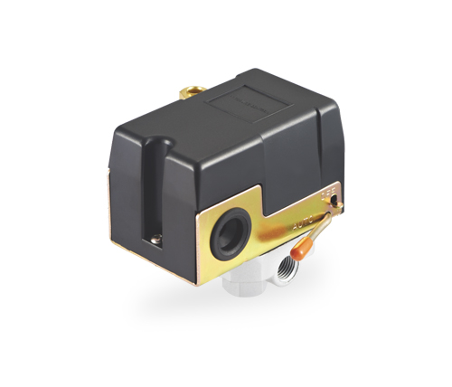
ERQ-1 Series Air-relief Customized Setting Pressure Switch for Air Compressors
An air compressor converts mechanical energy into compressed air and stores that air in a receiver tank or directly supplies it to pneumatic equipment. During operation, the pressure inside the system rises and falls according to air consumption. If the compressor continues operating after the required pressure has been reached, the system may experience excessive pressure, unnecessary energy consumption, component wear, or safety concerns.
A pressure switch solves this problem by sensing the pressure within the compressor system. It uses a pressure-sensitive mechanism to compare the actual system pressure with a predetermined setting. When pressure falls to the cut-in point, the switch closes or activates the electrical circuit so that the compressor can start. When pressure rises to the cut-out point, the switch opens or deactivates the circuit so that the compressor can stop.
The difference between the cut-in and cut-out values is commonly referred to as the pressure differential. This differential allows the compressor to operate within a practical pressure band rather than switching on and off continuously. Correct adjustment of the pressure band is important because excessively frequent cycling can increase motor stress, contact wear, and energy consumption.
In addition to regulating compressor operation, a pressure switch may include an air-relief mechanism. This mechanism releases residual pressure from a selected part of the compressor discharge line when the compressor stops. By reducing the pressure that the motor must overcome during the next start, the air-relief feature can support smoother starting and help reduce mechanical stress.
The ERQ-1 Series is an air-relief pressure switch developed specifically for air compressors. It combines electrical pressure control with a selectable pressure-release function and configurable mechanical connections. The product is designed to monitor compressor pressure, activate or deactivate the compressor at selected thresholds, and release excess or residual air pressure where required.
The series supports rated voltages from 110V to 240V and a rated current of 16A. This electrical range makes it suitable for many single-phase compressor control systems, provided that the voltage, current, motor characteristics, and installation conditions are correctly matched. The product operates at both 50 Hz and 60 Hz power frequencies, supporting use in different regional electrical environments.
The stated minimum cut-in pressure is 20 PSI, while the maximum cut-out pressure is 175 PSI. Standard pressure configurations include 80–110 PSI and 90–120 PSI, while customized pressure settings can be arranged according to the application. This combination of standard availability and customized configuration gives buyers a practical balance between convenience and technical flexibility.
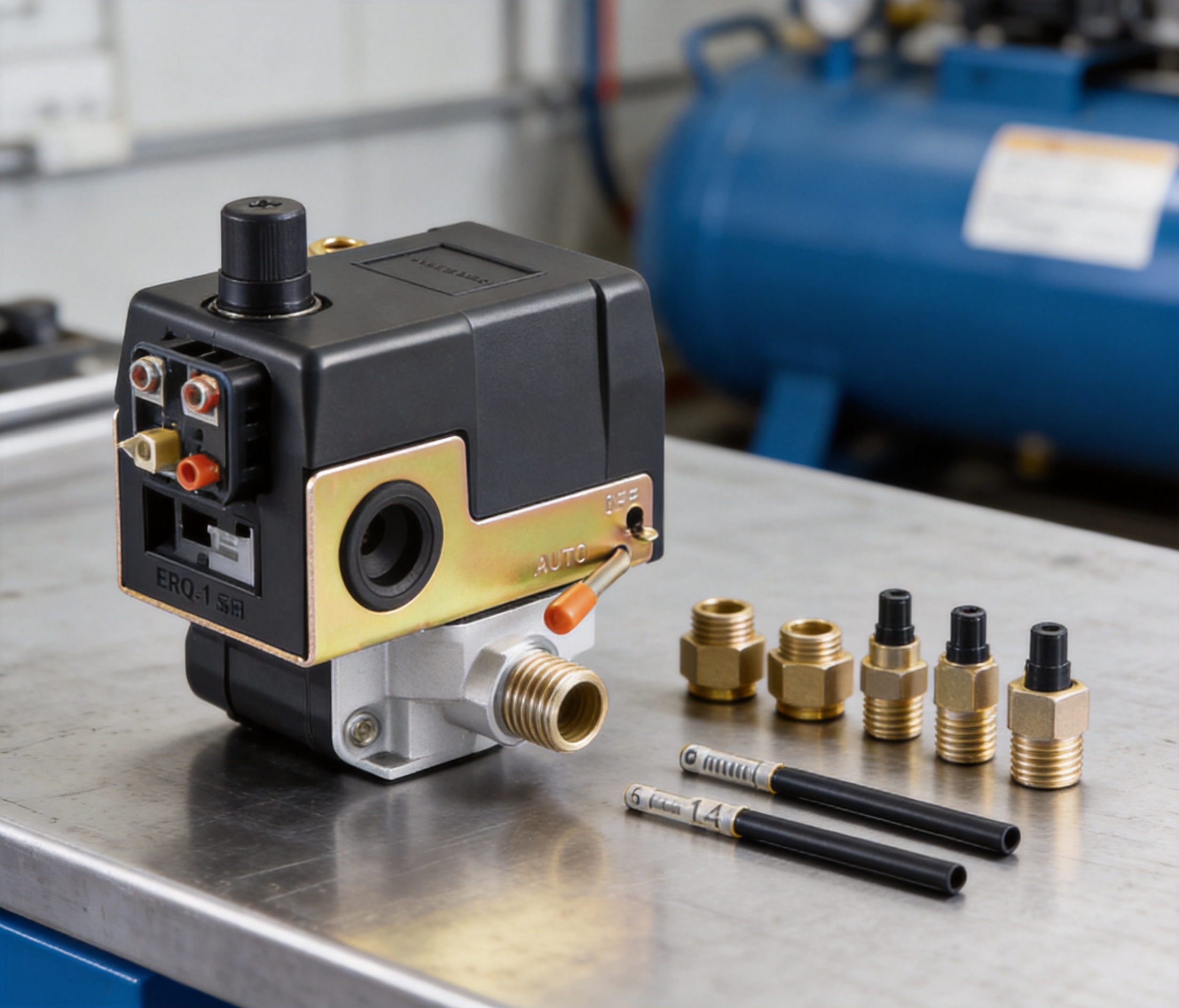
The ERQ-1 Series can be supplied with one-way or four-way screw configurations. The standard female screw size is 1/4 inch, and the air-relief valve can be configured for a 6 mm pipe or a 1/4-inch pipe. Hydraulic connections and the external housing can also be adapted according to customer requirements.
| Specification | ERQ-1 Series Information |
|---|---|
| Product type | Air-relief customized setting pressure switch |
| Primary application | Air compressors |
| Rated voltage | 110V–240V |
| Power frequency | 50/60Hz |
| Rated current | 16A |
| Minimum cut-in pressure | 20 PSI |
| Maximum cut-out pressure | 175 PSI |
| Standard pressure ranges | 80–110 PSI and 90–120 PSI |
| Screw configuration | One-way or four-way |
| Standard screw size | Female 1/4 inch |
| Air-relief valve options | 6 mm pipe or 1/4-inch pipe |
| Maximum working temperature | 40°C |
| Warranty | One year |
The technical data should be reviewed together with the compressor motor rating, receiver capacity, working pressure, electrical protection, ambient conditions, and applicable safety requirements. A pressure switch should never be used beyond its stated electrical, mechanical, or temperature limits.
The air-relief function is one of the defining features of the ERQ-1 Series. When a compressor stops, compressed air may remain trapped between the compressor outlet and the check valve or receiver connection. If the motor attempts to restart while this section remains pressurized, the compressor can face a higher starting load.
By releasing residual air through the air-relief valve, the pressure switch can help reduce the initial resistance experienced by the compressor during restart. This may contribute to smoother motor starting, especially in applications where the compressor starts frequently or where the compressor has limited starting torque.
The air-relief feature can also support longer service life for related components. Lower starting stress may reduce strain on the motor, crank mechanism, piston assembly, belt drive, and electrical switching components. It does not replace a pressure relief valve, overload protector, check valve, or other required safety device, but it serves an important operational role in the compressor control circuit.
Customers can select an air-relief valve suitable for either a 6 mm pipe or a 1/4-inch pipe. This option allows the pressure switch to be matched to the existing tubing arrangement and installation space. When specifying the product, users should confirm the actual tube outside diameter, connection method, pressure rating, and compatibility with the compressor assembly.
Compared with pressure switches that only open and close the electrical circuit, an air-relief model provides an additional control function in the same compact component. This can simplify the compressor layout, reduce the number of separate fittings, and make maintenance more convenient when the system is designed around the integrated pressure switch.
Air compressors are used in many operating environments, and not every application requires the same pressure range. An automotive repair shop may require a pressure band suitable for impact tools and tire service equipment. A workshop may need a moderate pressure setting for pneumatic assembly tools. An industrial machine may require a specific cut-in and cut-out combination based on production-cycle demand.
The ERQ-1 Series supports customized pressure settings so that the compressor control point can be aligned with the actual requirements of the equipment. Standard options such as 80–110 PSI and 90–120 PSI are useful for common applications, while customized settings can be considered when the system requires another operating range within the product’s rated limits.
Customized pressure settings provide several advantages. First, they can help prevent the compressor from operating at a pressure higher than necessary. Excessively high pressure may increase energy consumption and place additional stress on hoses, valves, seals, and pneumatic tools. Second, the setting can be coordinated with the minimum pressure required by downstream equipment. Third, a suitable pressure differential can help reduce unnecessary start-stop cycling.
Customers requesting customized settings should provide detailed application information. Important data includes the preferred cut-in pressure, preferred cut-out pressure, compressor motor rating, receiver tank capacity, operating frequency, expected duty cycle, working temperature, and type of downstream equipment. This information helps ensure that the selected configuration is appropriate for the complete system rather than only for one component.
The cut-in pressure should be high enough to maintain the performance of connected equipment but low enough to prevent excessive compressor cycling. The cut-out pressure should provide sufficient stored air without exceeding the safe working pressure of the receiver, piping, and accessories.
The pressure differential should also be considered. A very narrow differential may cause frequent starts, particularly when the system has fluctuating air demand or a small receiver. A wider differential may reduce cycling but can create greater variation in the air supply pressure. The correct balance depends on the compressor size, air demand pattern, receiver capacity, and the operating requirements of the pneumatic equipment.
Pressure settings should be verified with a reliable pressure gauge during commissioning. Calibration and adjustment should be performed by qualified personnel who understand the electrical and pneumatic hazards associated with compressed-air equipment.
The ERQ-1 Series is rated for 110V to 240V and 50/60Hz operation, with a rated current of 16A. This broad voltage range supports use in many standard compressor control systems. However, rated current should not be interpreted in isolation. The starting current of an electric motor can be significantly higher than its normal running current, and the actual switching suitability depends on the motor type, load, power factor, duty cycle, and electrical circuit design.
Before installation, the user should compare the pressure switch rating with the compressor motor’s nameplate data. If the motor current or starting demand exceeds the suitable switching capacity, an external contactor or relay may be required. Appropriate fuses, circuit breakers, overload protection, grounding, and disconnecting devices should also be installed in accordance with local electrical standards.
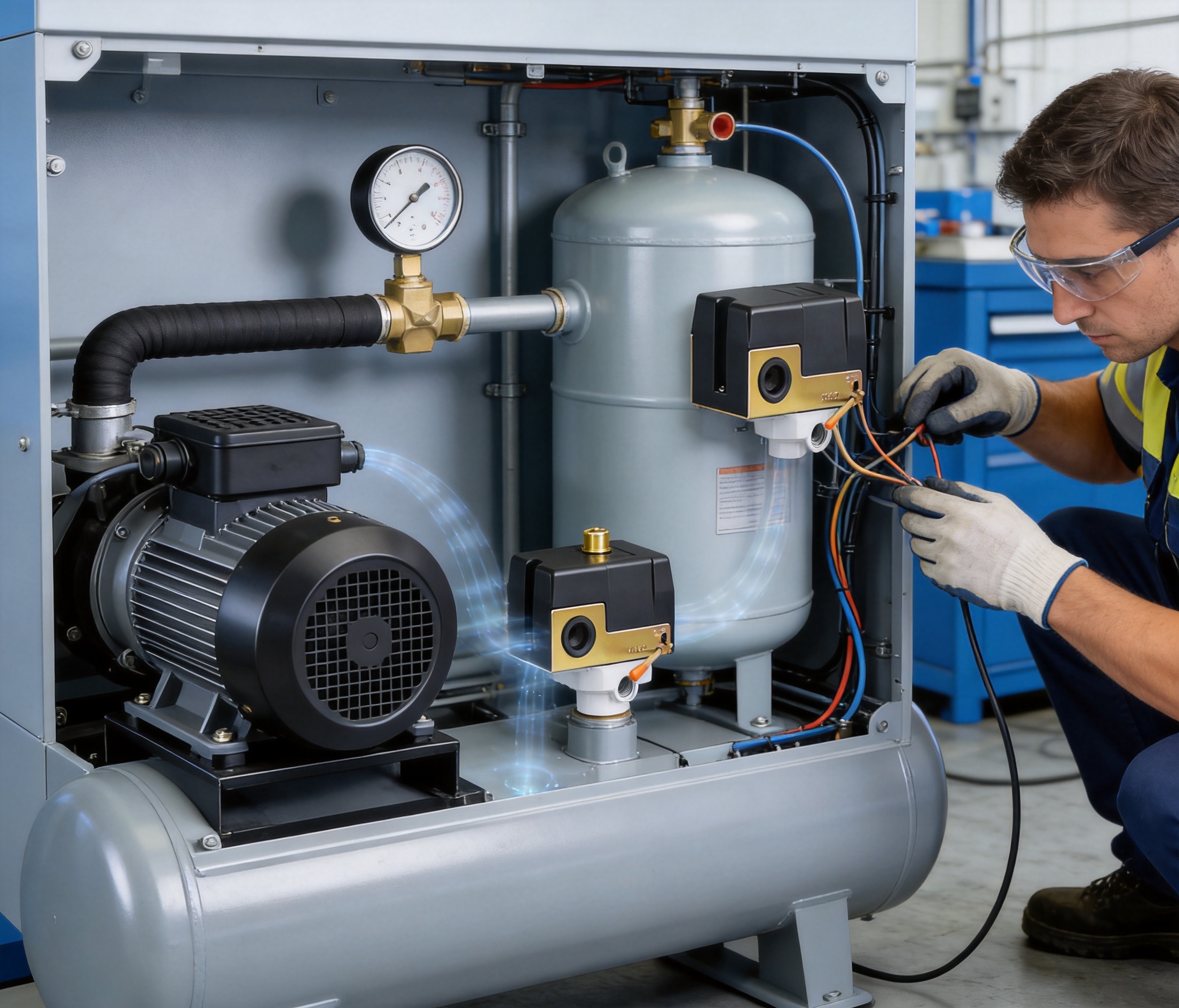
The pressure switch should be installed only by qualified electrical personnel. The power supply must be disconnected before wiring, adjustment, inspection, or maintenance. Wires should be properly sized and securely terminated, and the enclosure should be protected from moisture, oil contamination, excessive dust, and mechanical impact.
Because the product can be configured for different compressor applications, electrical connections should be checked against the relevant wiring diagram before commissioning. Incorrect wiring may cause the compressor to run continuously, fail to start, start unexpectedly, or operate without the intended pressure protection.
The ERQ-1 Series offers one-way and four-way screw configurations. This gives equipment designers and installers more freedom when arranging the pressure switch, gauge, safety valve, discharge line, and other fittings. A one-way configuration can be suitable for a simpler installation, while a four-way configuration may support a more integrated control manifold.
The standard female connection is 1/4 inch, but the hydraulic connection can be customized according to customer requirements. Connection selection should take into account thread type, sealing method, pipe material, available space, vibration, and the pressure rating of the complete assembly.
Correct mechanical installation is essential. The pressure switch should be mounted in a position where it can sense system pressure accurately and where the air-relief outlet can function without obstruction. The pipe should be clean and free from metal chips, sealing compound debris, oil sludge, or other particles that could interfere with the pressure mechanism or air-relief valve.
Thread sealant should be applied carefully. Excessive sealant can enter the pressure passage and restrict sensing or release. The switch should be tightened using suitable tools and torque practices rather than by applying force to the electrical housing or adjustment components. Any tubing connected to the air-relief valve should be routed away from sharp edges, high-temperature surfaces, moving parts, and areas where it could be crushed.
The ERQ-1 Series offers several practical advantages compared with basic pressure switches that are available only in one fixed configuration.
Fixed-setting products may force the user to adapt the compressor system to the pressure switch. The ERQ-1 Series takes the opposite approach by allowing the pressure settings to be selected according to the application. This is especially valuable for original equipment manufacturers and distributors serving multiple markets.
A standard pressure switch may control the electrical circuit without providing an integrated air-relief function. The ERQ-1 Series combines both functions in one product, helping reduce residual discharge pressure during compressor shutdown and restart. This can simplify system design and reduce the need for separate components.
The 110V–240V rating and 50/60Hz frequency compatibility make the series suitable for a wide range of regional electrical systems. Buyers may avoid managing multiple pressure switch models when the same basic series can be configured for different markets, subject to correct application verification.
One-way and four-way screw options, a standard female 1/4-inch connection, and customized hydraulic connections provide useful mechanical flexibility. This can shorten installation time and reduce the need for additional adapters.
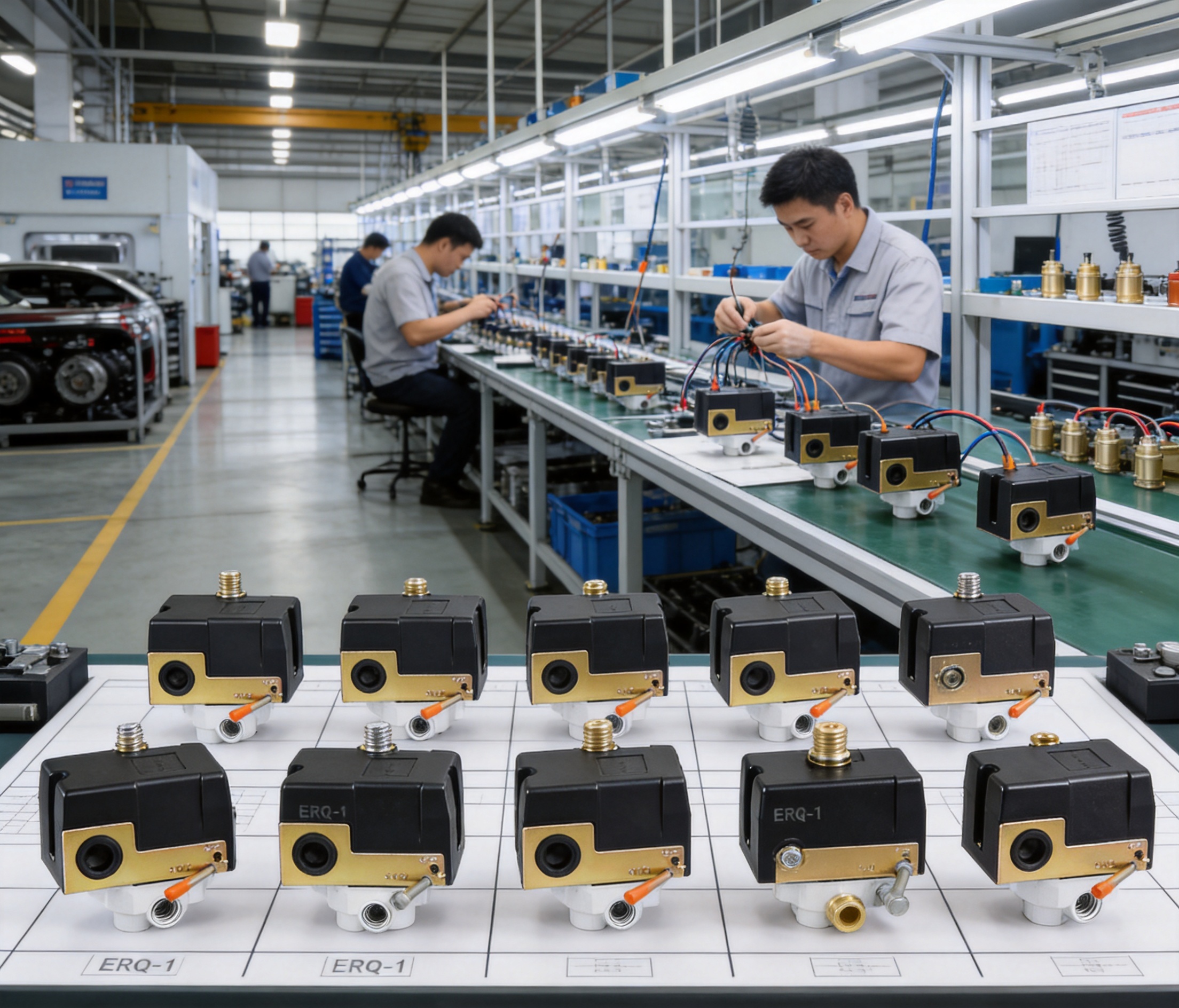
Customers can request changes to the housing, hydraulic connection, air-relief pipe size, and pressure setting. This level of configuration is more suitable for private-label programs, equipment manufacturers, and customers who require a product that fits an existing compressor design.
The product is intended for workshops, industrial environments, and automotive repair shops rather than only for light household use. Its operating specifications, configurable structure, and pressure-control function make it suitable for systems where reliability, repeatability, and serviceability are important.
Taizhou Edwin Electric Co., Ltd., operating under the Edwin Pump name, was founded in 2008 and has developed an integrated manufacturing model covering independent research and development, mass production, and global export. Although the company is widely associated with water pumps and water-treatment peripheral products, its engineering and manufacturing experience also supports the development of related pressure-control components.
The company’s broader product portfolio includes deep well pumps, submersible pumps, domestic booster pumps, circulation pumps, solar water pumps, intelligent booster pumps, and other water-system products. This experience provides exposure to pressure management, motor control, fluid movement, electrical protection, mechanical connections, and system-level performance.
For a pressure switch manufacturer, system knowledge is valuable. A pressure switch does not operate independently; it is connected to a motor, pressure vessel, piping network, check valve, gauge, relief device, and downstream load. Experience with complete pumping and fluid-control systems can help a manufacturer understand how pressure components behave in real installations.
The company’s manufacturing structure is supported by related business organizations established to serve procurement planning, order tracking, cross-border delivery, and foreign-trade services. This organization is useful for international customers who need product coordination, customized specifications, order communication, and delivery support in addition to the physical product.
Independent research and development allows product designs to be adjusted in response to market requirements. For the ERQ-1 Series, this can include different pressure ranges, air-relief arrangements, screw configurations, housing requirements, and hydraulic connections. Such adaptability is particularly important when customers have equipment-specific requirements.
The company has also invested in new energy and intelligent technology since 2018, expanding into solar water pumps and intelligent booster pumps. This development direction demonstrates an interest in energy efficiency, automation, and modern control systems. While the ERQ-1 Series is a mechanical pressure controller, the same engineering perspective can support reliable integration with wider compressor and equipment-control systems.
Mass production requires more than the ability to assemble individual units. It requires stable sourcing, repeatable manufacturing procedures, inspection arrangements, production planning, and consistent packaging. A pressure switch must maintain reliable mechanical movement, electrical contact performance, pressure response, connection quality, and air-relief operation across production batches.
An integrated manufacturer can coordinate design changes, component procurement, assembly, inspection, and shipment more efficiently than a trading organization that depends entirely on external production. This can be important for customers who require recurring orders, stable specifications, replacement availability, and predictable lead-time planning.
Edwin Pump has supplied products to customers in international markets and has built experience in export documentation, product packaging, order coordination, and overseas delivery. This background can help reduce communication difficulties for customers purchasing pressure switches for distribution or equipment manufacturing.
Global buyers should still confirm the required inspection documents, electrical standards, packaging specifications, labeling, and destination-market requirements before placing an order. A professional supplier should be able to discuss these details during the quotation and order-confirmation stages.
Industrial workshops often use compressed air for pneumatic tools, cleaning equipment, assembly systems, and maintenance operations. The ERQ-1 Series can help keep receiver pressure within a selected working range, allowing tools to receive a dependable air supply while preventing unnecessary compressor operation.
Automotive repair shops commonly use air compressors for tire inflation, impact wrenches, spray equipment, air ratchets, and cleaning tasks. Since air demand can change quickly, a suitable cut-in and cut-out range is important. The air-relief function can also be beneficial where the compressor starts repeatedly during a busy workday.
Small and medium pneumatic systems may require a compact control component that can be adjusted to the equipment’s pressure requirements. The ERQ-1 Series can be considered for systems using standard 1/4-inch connections or customized hydraulic arrangements.
Compressor manufacturers and equipment builders may require a pressure switch with a particular housing, pressure setting, pipe connection, or air-relief arrangement. The customization options make the product suitable for OEM programs in which the pressure switch must fit an established product design.
Distributors and maintenance companies may use the series as a replacement option for compatible compressor pressure switches. Before substitution, the buyer should verify voltage, current, cut-in pressure, cut-out pressure, thread dimensions, air-relief tubing, mounting arrangement, and environmental conditions.
Before installation, inspect the pressure switch for transport damage, cracks, loose parts, blocked ports, or damaged terminals. Confirm that the model configuration corresponds to the compressor’s electrical and pressure requirements.
Disconnect the compressor from the power supply and fully depressurize the relevant pneumatic section before beginning installation. Never rely only on the pressure switch to isolate stored energy. Compressed air can remain in tanks, pipes, hoses, and fittings even after the motor has stopped.
Install the pressure connection using a compatible fitting and an appropriate sealing method. Keep the pressure passage clean. Do not use excessive force on the housing or adjustment mechanism. Ensure that the air-relief pipe is correctly connected and not obstructed.
Wire the product according to the applicable electrical diagram. Verify the supply voltage, motor current, protective devices, grounding arrangement, and direction of control operation. If an external contactor is used, confirm that the contactor coil and switching circuit are compatible with the pressure switch.
After installation, inspect all connections before applying power. Slowly pressurize the system and check for air leakage. Observe the pressure gauge as the compressor starts and stops. Confirm that the compressor starts at or near the selected cut-in pressure and stops at or near the selected cut-out pressure.
Test the air-relief function during a controlled commissioning procedure. The released air should be directed safely, and the outlet should not be aimed toward people, electrical components, or contaminated work surfaces. If the switch operates outside the expected range, disconnect the system and investigate the installation, gauge accuracy, pressure setting, wiring, and mechanical connection.
Regular inspection can help maintain reliable pressure control. Maintenance personnel should check the pressure switch housing, electrical terminals, pressure connection, air-relief pipe, and surrounding components. Signs of concern may include air leakage, unstable switching, contact overheating, delayed compressor starting, continuous compressor operation, or unusual pressure fluctuation.
The pressure switch should be kept free from excessive dust, oil accumulation, water spray, and corrosive chemicals. The maximum working temperature is specified as 40°C, so the switch should not be mounted close to exhaust manifolds, hot compressor heads, heaters, or other high-temperature sources.
If pressure settings are changed, the new values should be recorded and verified with a calibrated gauge. Uncontrolled adjustment may cause the compressor to operate outside the safe range of the receiver or connected equipment.
Electrical inspection should be conducted with the power disconnected. Loose terminals can produce heat and intermittent operation. Damaged wires, burned contacts, cracked insulation, or signs of moisture ingress should be addressed immediately.
The product is supplied with a one-year warranty. Warranty coverage is normally dependent on correct installation, proper application, and compliance with the specified operating limits. Customers should retain purchase records, model information, batch information where available, and installation details to support service communication.
The first selection factor is the compressor’s electrical requirement. Confirm the supply voltage, frequency, motor running current, motor starting characteristics, and whether direct switching or an external contactor is required.
The second factor is pressure. Determine the required cut-in and cut-out values, the normal working pressure of the pneumatic tools or equipment, and the maximum safe pressure of the receiver and piping. The selected settings must remain within the pressure switch and compressor system limits.
The third factor is the mechanical connection. Check whether the compressor requires a one-way or four-way arrangement, whether the connection is female 1/4 inch, and whether a customized hydraulic connection is needed.
The fourth factor is the air-relief arrangement. Select the 6 mm or 1/4-inch pipe option according to the existing discharge-line tubing and the physical layout of the compressor.
The fifth factor is the operating environment. Consider temperature, moisture, oil vapor, dust, vibration, installation orientation, and accessibility for maintenance. The product should be used only in conditions compatible with its stated maximum working temperature and mechanical limitations.
| Selection Question | Information to Confirm |
|---|---|
| What is the electrical supply? | 110V–240V, 50/60Hz, motor current, and starting demand |
| What pressure is required? | Desired cut-in, cut-out, differential, and maximum system pressure |
| Which connection is needed? | One-way or four-way arrangement and thread dimensions |
| Which air-relief pipe is suitable? | 6 mm or 1/4-inch tubing compatibility |
| Where will the unit operate? | Temperature, dust, moisture, vibration, and service access |
| Is customization required? | Housing, hydraulic connection, pressure setting, and labeling requirements |
For distributors, a configurable pressure switch can help serve several customer segments without requiring a completely different supplier for every pressure range or connection type. Standard configurations can support routine orders, while customized options can address special compressor designs.
For OEM buyers, the ability to request a specific housing, hydraulic connection, pressure setting, or air-relief configuration can reduce the need for field modification. A component designed around the equipment can improve assembly consistency and reduce the risk of improvised adapters or adjustments.
For international procurement teams, a manufacturer with experience in product development, mass production, and export coordination can provide broader support throughout the purchasing process. Technical specifications should be confirmed in writing before production, especially when the buyer requires private labeling, special packaging, customized settings, or destination-specific documentation.
The company’s wider product range also creates opportunities for coordinated procurement. Buyers sourcing pumps, booster systems, circulation equipment, solar water-pumping products, or water-treatment accessories may be able to consolidate supplier communication and shipment planning through the same manufacturing and export network.
The primary purpose is to monitor air compressor pressure and control compressor starting and stopping at selected pressure thresholds. It also includes an air-relief function to release residual pressure from the compressor discharge section when required.
The rated voltage range is 110V to 240V, with a power frequency of 50/60Hz. The electrical system must still be checked against the motor’s current, starting demand, circuit design, and applicable local requirements.
The rated current is 16A. Because compressor motors can draw a higher current during startup, users should verify whether direct switching is suitable or whether an external contactor and overload protection are necessary.
The listed minimum cut-in pressure is 20 PSI and the maximum cut-out pressure is 175 PSI. Standard pressure ranges include 80–110 PSI and 90–120 PSI. Other settings may be customized according to customer requirements within the applicable product limits.
The air-relief valve releases residual compressed air from a selected section of the compressor system after shutdown. This can reduce restart resistance and support smoother compressor starting. It is not a substitute for a safety relief valve or other required protection device.
The air-relief valve can be configured for a 6 mm pipe or a 1/4-inch pipe. The correct selection depends on the tubing used in the compressor assembly.
Yes. Available customization options include the external housing, hydraulic connection, air-relief valve pipe size, and pressure setting. Customers should provide complete technical requirements before quotation and production confirmation.
The product can be supplied with a one-way or four-way screw arrangement. The standard screw size is a female 1/4-inch connection, while other hydraulic connection requirements may be discussed for customized projects.
The listed maximum working temperature is 40°C. Installation should avoid direct exposure to high-temperature surfaces, hot compressor components, and other heat sources.
Typical applications include industrial workshops, automotive repair shops, general pneumatic equipment, air compressor systems, OEM machinery, and replacement-control applications.
Installation should be performed by qualified personnel after disconnecting electrical power and releasing stored compressed air. The pressure connection, air-relief pipe, wiring, protective devices, and operating settings should all be checked before commissioning.
No. The pressure switch controls the compressor based on pressure, while a pressure gauge provides visual pressure indication. Both components may be required for safe monitoring and operation.
No. A pressure switch and an independent safety relief valve perform different functions. The compressor system should include all safety devices required by its design and applicable regulations.
The product information specifies a one-year warranty. Customers should confirm warranty terms, application conditions, documentation requirements, and service procedures with the supplier before purchase.
The ERQ-1 Series Air-Relief Customized Setting Pressure Switch is designed to provide dependable pressure control for air compressor systems. Its main advantages include adjustable pressure settings, integrated air relief, 110V–240V electrical compatibility, a 16A rated current, one-way and four-way screw options, and configurable hydraulic and housing arrangements.
These features make the series more adaptable than a basic fixed-setting pressure switch. It can be configured for standard compressor applications while also supporting OEM and project-specific requirements. The air-relief function adds practical value by helping reduce residual discharge pressure during compressor restart, while the adjustable pressure range allows the equipment to operate closer to its actual application requirements.
Supported by Taizhou Edwin Electric Co., Ltd.’s experience in independent research and development, mass production, global export, pump technology, and intelligent equipment development, the product is positioned as a flexible control component for international compressor markets. Correct selection, professional installation, suitable electrical protection, and regular maintenance remain essential to achieving reliable performance.
1. Product technical data supplied for the ERQ-1 Series Air-Relief Customized Setting Pressure Switch for Air Compressors.
2. Manufacturer application information concerning pressure control, air-relief operation, customization options, and compressor applications.
3. General industrial guidance on compressed-air system design, pressure control, motor protection, and pneumatic safety.
4. General electrical installation principles for low-voltage motor control equipment and pressure-operated switching devices.
5. General maintenance practices for air compressors, receiver tanks, pneumatic piping, pressure switches, gauges, and relief devices.

serieswatershortageprotectionvoltagestabilizationstainlesssteelverticalmultistagepump.jpg "EVR(S) Series Water Shortage Protection Voltage Stabilization Stainless Steel Vertical Multistage Pump")
edwina@edwin-pump.com
+86-13586290903 (WhatsApp)
Xuri Gongliang Cutting Tool Entrepreneurship Park, Wenqiao Town, Wenling City, Taizhou City, Zhejiang Province, China

High Performance Smart Pump Factory


 English