
edwina@edwin-pump.com

View All Products
en
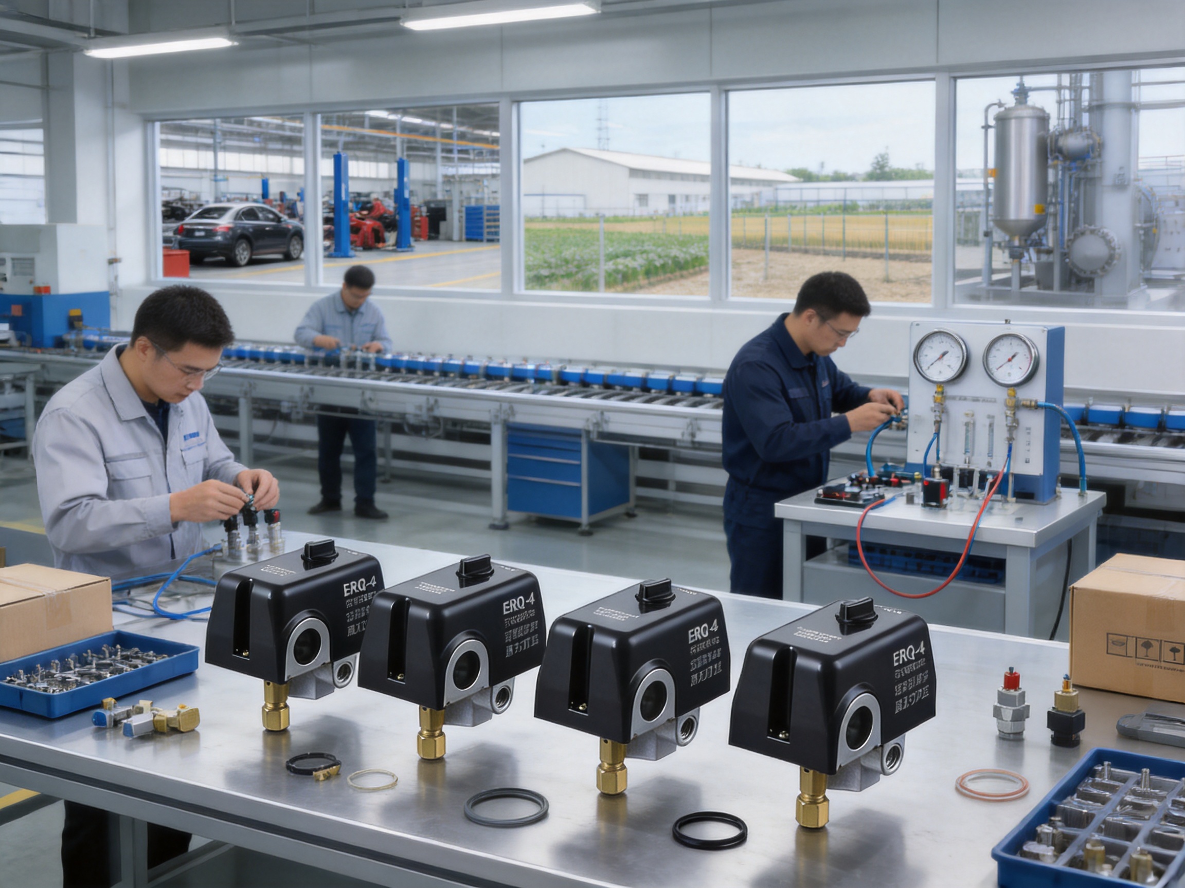
Reliable pressure control is essential to the safe, efficient, and long-lasting operation of an air compressor. A pressure switch performs this task by monitoring system pressure and controlling when the compressor motor starts or stops. Although the operating principle is simple, the quality of the switch has a direct effect on energy consumption, equipment protection, maintenance requirements, and workplace safety.
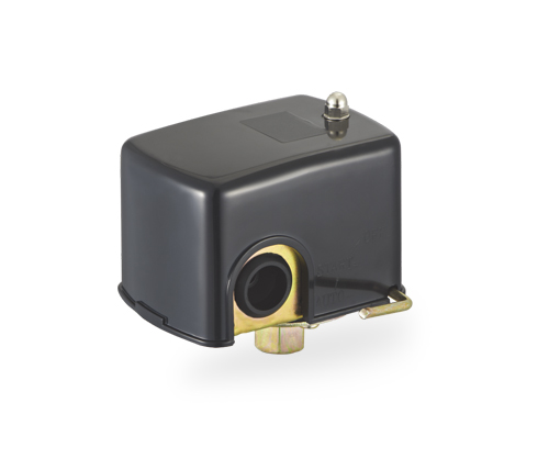
The ERQ-4 Series pressure switch is designed for air compressor applications that require dependable pressure sensing, practical electrical compatibility, and protection against water exposure. With a current rating of up to 12A, configurable pressure settings, optional hydraulic connections, and an air-relief valve with delayed closing, the series is suitable for workshops, industrial facilities, automotive repair environments, agricultural installations, and other compressed-air systems.
Its waterproof-oriented construction is particularly valuable in locations where condensation, splashing, humidity, or occasional water exposure may affect conventional pressure switches. At the same time, the switch provides automatic compressor control by activating the motor when pressure falls below the cut-in point and stopping it when the cut-out pressure is reached.
This article examines the product’s construction, operating principle, technical parameters, application advantages, customization options, installation considerations, quality controls, and the manufacturing capabilities behind its production. It also explains how purchasers can select the correct configuration and integrate the pressure switch into a safe and reliable compressed-air system.
An air compressor converts mechanical energy into compressed air and stores that air in a receiver tank or pressure vessel. As air is consumed by tools, machinery, valves, or production processes, the pressure inside the system gradually decreases. Without automatic control, the compressor would either run continuously or require manual starting and stopping.
A pressure switch provides automatic control. It senses the pressure in the compressed-air system and uses an electrical contact mechanism to control the compressor motor circuit. When pressure reaches the lower operating limit, known as the cut-in pressure, the switch closes or changes its electrical state so that the compressor starts. When pressure reaches the upper operating limit, known as the cut-out pressure, the switch opens or changes state, stopping the compressor.
This automatic cycle offers several important benefits:
• It maintains pressure within a usable operating range.
• It reduces the need for continuous operator supervision.
• It helps prevent unnecessary compressor operation.
• It protects the system from excessive pressure when correctly selected and installed.
• It supports more stable operation of pneumatic equipment.
• It can reduce motor wear caused by incorrect manual switching.
The difference between cut-out pressure and cut-in pressure is commonly called the pressure differential or operating range. For example, a pressure switch configured for a 30–60 psi cycle starts the compressor when pressure falls to approximately 30 psi and stops it when pressure rises to approximately 60 psi. Actual settings should be verified during installation because performance can vary according to system design, gauge accuracy, installation conditions, and the selected pressure-switch configuration.
The ERQ-4 Series is a mechanical pressure controller intended primarily for air compressors. It combines a pressure-sensing mechanism, electrical switching contacts, a protective housing, and optional connection arrangements in one compact control component.
The product information identifies a 12A current rating, a pressure range extending from 20 psi to 175 psi, 50/60Hz frequency compatibility, and a maximum working temperature of 40°C. The listed pressure settings include 20–50 psi, 30–60 psi, 40–70 psi, 50–80 psi, 95–125 psi, and 135–175 psi. These configurations allow buyers to match the switch to different receiver sizes, compressor capacities, pneumatic tools, and operating requirements.
The product title indicates compatibility with 110V to 240V electrical systems, while the technical parameter list also states a rated voltage of 380V. Because electrical ratings must be confirmed for every application, buyers should verify the required voltage, phase arrangement, motor load, wiring configuration, and applicable certification before ordering or installation. The correct configuration may depend on the specific model variation and customer requirements.
The pressure switch is described as impermeable to water or waterproof-oriented. This feature is intended to improve resistance to water ingress and enhance service reliability in humid or wet environments. However, the stated protection degree is IP20. IP20 does not indicate complete protection against water, so the switch should not be treated as suitable for immersion, direct high-pressure washing, or unprotected outdoor exposure unless an appropriate enclosure and installation method are provided.
The ERQ-4 Series can be supplied with different hydraulic connection options, including 1/4-inch male or female configurations. A one-way or four-way screw arrangement can also be selected. These options simplify integration into different compressor layouts and may reduce the need for additional adapters.
| Parameter | Available or Listed Specification | Application Significance |
|---|---|---|
| Product type | Mechanical pressure controller | Provides automatic pressure-based compressor control |
| Primary application | Air compressors | Suitable for workshops, industrial systems, and service environments |
| Minimum cut-in pressure | 20 psi | Lowest listed starting-pressure setting |
| Maximum cut-out pressure | 175 psi | Highest listed stopping-pressure setting |
| Pressure settings | 20–50, 30–60, 40–70, 50–80, 95–125, and 135–175 psi | Allows selection according to compressor and receiver requirements |
| Rated current | 12A | Supports suitable motor-control applications within the rated load |
| Voltage information | 110–240V product designation; 380V listed in technical data | Must be confirmed against the exact model and electrical system |
| Frequency | 50/60Hz | Compatible with common commercial power frequencies |
| Maximum working temperature | 40°C | Installation should account for ambient and enclosure temperature |
| Protection degree | IP20 | Requires appropriate placement and additional protection against water |
| Hydraulic connection | 1/4-inch male or female options | Supports different piping and manifold arrangements |
| Screw configuration | One-way or four-way | Offers installation flexibility |
| Air-relief valve | Available with delayed closing system | Helps unload pressure during compressor restart |
| Warranty | One year | Provides a defined period of product support |
The table summarizes the supplied product information. Electrical and pressure specifications should always be checked against the final product label, technical drawing, purchase order, and installation instructions. A pressure switch is a safety-related control component, and assumptions about voltage or pressure compatibility should be avoided.
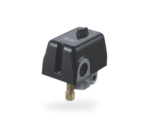
ERQ-4 Series 12A 110V to 240V Impermeable to Water Pressure Switch Used in Air Compressors
The ERQ-4 Series uses a mechanical pressure-sensing assembly. System pressure acts on an internal diaphragm, piston, or similar sensing element. As pressure changes, the sensing element moves against a calibrated spring force. When the pressure reaches the selected threshold, the mechanism changes the position of the electrical contacts.
During a normal operating cycle, compressed air is consumed from the receiver tank. The pressure falls gradually until it reaches the cut-in setting. At this point, the switch commands the compressor to start. The compressor then replenishes the receiver tank. Once the pressure reaches the selected cut-out setting, the switch interrupts the motor circuit and the compressor stops.
The pressure differential is important because a system with an excessively narrow differential may cause frequent starts and stops. This condition, known as short cycling, can increase motor heating, contact wear, and energy consumption. A differential that is too wide may produce pressure fluctuations that affect pneumatic tools or production equipment. The available ERQ-4 settings allow the user to select a practical operating range for the application.
Pressure settings must be selected according to the compressor manufacturer’s recommendations, receiver-tank rating, hose and fitting limitations, pneumatic equipment requirements, and applicable safety regulations. The maximum rated pressure of the switch does not automatically mean that the complete compressor system can safely operate at that pressure.
One notable feature of the ERQ-4 Series is the availability of an air-relief valve with a delayed closing system. This valve is designed to release residual pressure from the compressor discharge line after the compressor stops. Removing this trapped pressure can reduce the load placed on the motor during the next startup.
When a compressor stops, compressed air may remain in the pipe between the compressor outlet and the check valve or receiver inlet. If the motor attempts to restart while this section is still pressurized, the compressor may need to overcome unnecessary back pressure. This can result in difficult starting, increased current draw, contact stress, and premature motor wear.
An air-relief valve with delayed closing is intended to open during the appropriate part of the stop-and-start cycle and then close when the compressor begins producing air. The precise function depends on the pressure-switch design and the compressor’s check-valve arrangement. Correct tubing size and connection are essential. The product options indicate air-relief valve tubing of either 6 mm or 1/4-inch diameter.
This feature can be especially useful in systems that experience frequent cycling or use motors with limited starting torque. It may also contribute to smoother operation and longer service life. Nevertheless, it should not replace a correctly sized check valve, properly designed discharge piping, or suitable motor protection.
Air compressor installations are often exposed to environmental conditions that can reduce the life of electrical controls. Automotive repair shops may use water-based cleaning equipment. Agricultural facilities can experience humidity, dust, and condensation. Workshops may have open doors, temperature variations, or occasional liquid splashes. In industrial areas, pressure switches may be installed close to washdown zones or fluid-handling equipment.
The ERQ-4 Series is designed with an impermeable-to-water concept intended to limit water ingress into the pressure-switch housing. By reducing the likelihood that moisture reaches sensitive electrical components, the design can help maintain more consistent switching performance and reduce corrosion-related failures.
Its environmental advantages may include:
• Better resistance to occasional splashing and humid conditions than an unprotected conventional switch.
• Reduced risk of internal contamination caused by moisture.
• Improved durability in workshops and service areas.
• Greater flexibility when the compressor must be installed near water-using equipment.
• Potentially longer contact and mechanism life when moisture is a major environmental concern.
It is important to interpret water resistance accurately. The listed IP20 protection degree means that the switch still requires careful placement. It should be shielded from direct spray, standing water, heavy condensation, and immersion. If the application involves outdoor exposure, washdown cleaning, or high-pressure water jets, an additional enclosure with a suitable ingress-protection rating may be necessary.
Many basic pressure switches are supplied with only one standard pressure setting, limiting their usefulness across different compressor systems. The ERQ-4 Series provides several pressure-setting combinations across a broad operating range. This allows distributors, equipment manufacturers, and service companies to select a configuration that corresponds to the required cut-in and cut-out values.
The available settings cover lower-pressure workshop applications as well as higher-pressure systems. This reduces the need to redesign the control circuit or use improvised adjustment methods. It also supports more consistent product selection for different equipment models.
The 12A rating makes the series suitable for many compact and medium-duty compressor control applications, provided the motor’s starting and running characteristics remain within the switch’s electrical limits. The stated 50/60Hz compatibility supports use in markets with either common commercial frequency.
The product information also refers to 110V–240V compatibility while listing 380V in the technical data. This suggests that model variants or electrical configurations may be available. Confirming the precise rating before purchase is essential, but the availability of configurable electrical options can be an advantage for export-oriented equipment manufacturers and international distributors.
The choice of 1/4-inch male or female hydraulic connection, together with one-way or four-way screw configurations, allows the switch to be matched to different piping layouts. This can simplify assembly, reduce extra fittings, and improve compatibility with existing compressor manifolds.
Connection flexibility is particularly valuable for original equipment manufacturers that produce several compressor models. Instead of using a completely different pressure switch for each layout, the manufacturer may be able to select a compatible connection option from the same product family.
The optional air-relief valve with delayed closing distinguishes the series from simple pressure switches that provide only electrical switching. By helping release residual discharge pressure, the valve can support easier motor restarting and reduce stress on the compressor assembly.
Water-resistant construction offers an advantage in applications where standard indoor electrical controls may experience premature failure. Although the switch still requires proper installation, its design is better aligned with humid or occasionally wet working environments than an entirely unprotected control device.
The product supports customized pressure settings, housing or cover requirements, hydraulic connections, air-relief valve tubing, and other customer-specific options. Customization is useful for private-label equipment, compressor manufacturers, importers, and project-based industrial procurement.
Compared with low-cost generic alternatives, a configurable product can reduce the engineering compromises associated with forcing one standard model into every application. It can also improve assembly efficiency and reduce the number of adapters or additional components required in production.
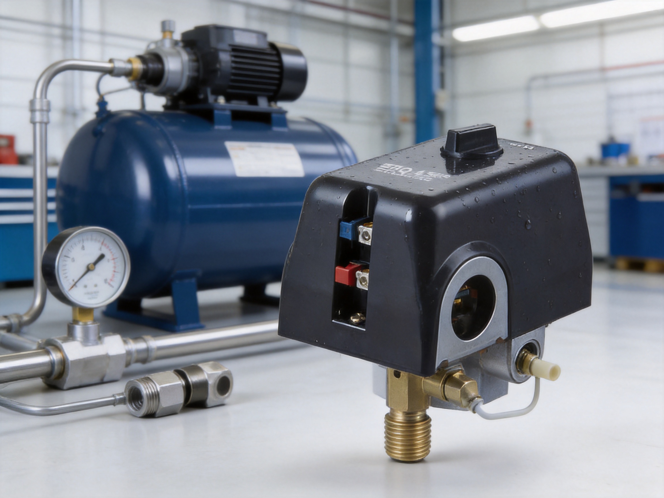
The pressure switch is supplied by Taizhou Edwin Electric Co., Ltd., an integrated manufacturing enterprise established in 2008. The company’s activities include independent research and development, mass production, and global export. Its broader product portfolio includes deep well pumps, submersible pumps, domestic booster pumps, circulation pumps, solar water pumps, intelligent booster pumps, and water-treatment peripheral products.
This broader product background is relevant to the pressure-switch product because pressure control is closely connected with pump and motor-system engineering. Experience with motors, hydraulic circuits, electrical controls, and water-related equipment helps a manufacturer understand how a mechanical pressure controller will perform in real operating environments.
The company’s manufacturing strengths can be considered in several areas:
Independent research and development provides the foundation for adapting products to changing market requirements. For a pressure switch, development work may involve pressure-sensing accuracy, contact reliability, spring calibration, housing design, connection compatibility, valve response, and environmental resistance.
Because the company also manufactures a wide variety of pumps, it is positioned to understand the interaction between pressure controls and motor-driven equipment. This application knowledge can support more practical product configurations and more useful technical communication with customers.
Mass production requires repeatable assembly procedures, controlled component sourcing, calibration methods, and traceable quality checks. Pressure switches contain small but important mechanical and electrical components. A slight variation in spring force, diaphragm behavior, contact alignment, or threaded connection can affect performance.
A structured production system helps control these variations. Standardized work instructions can ensure that components are assembled in the correct sequence. In-process inspection can identify dimensional or assembly problems before final testing. Final testing can verify switching response, pressure behavior, electrical continuity, and general operation.
The company has developed professional teams for procurement planning, order tracking, cross-border delivery, and foreign-trade services through related enterprises established in 2012. This international orientation is valuable to buyers who require clear order coordination, consistent documentation, packaging suitable for export, and communication across different time zones and markets.
For distributors and original equipment manufacturers, supply reliability involves more than the product itself. It also includes repeat ordering, configuration confirmation, lead-time coordination, packaging, labeling, and technical response. A manufacturer with established export experience can provide support across these stages.
A broad product portfolio can support one-stop procurement. Buyers sourcing pumps, pressure-control components, booster systems, and related accessories may reduce the number of separate suppliers involved in a project. This can simplify vendor qualification, product matching, shipment planning, and after-sales communication.
The company’s experience in solar water pumping and intelligent booster systems also indicates an interest in energy-efficient and technology-oriented products. While the ERQ-4 Series is a mechanical pressure controller rather than a smart electronic controller, it can serve as a dependable component in conventional compressor applications where straightforward automatic control is preferred.
A reliable pressure switch should be evaluated through both component quality and functional testing. The following quality-control stages are important for products in this category:
Incoming inspection should confirm that springs, diaphragms, electrical terminals, housings, valves, seals, and threaded components meet the required specifications. Materials must be suitable for the intended pressure, temperature, and environmental conditions.
Dimensional inspection should verify thread accuracy, connection geometry, housing fit, and the position of mounting features. Correct dimensions are essential for preventing leakage and ensuring compatibility with compressor manifolds.
Mechanical assembly inspection should confirm that the pressure-sensing mechanism moves smoothly and that springs, diaphragms, and contact mechanisms are installed correctly. Incorrect assembly can produce unstable switching or premature wear.
Pressure calibration should verify the cut-in and cut-out points for the selected configuration. Testing should account for the pressure differential and should be performed with suitable calibrated equipment.
Electrical testing should confirm contact continuity, insulation performance where applicable, terminal integrity, and switching behavior under the rated conditions. The actual motor load must not exceed the pressure switch’s rated capacity.
Leak testing should be conducted around hydraulic connections, the pressure-sensing chamber, and the air-relief valve. Even a small leak can cause inaccurate pressure readings or repeated compressor cycling.
Environmental inspection should verify that the housing is correctly assembled and that the water-resistant design has not been compromised by gaps, damaged seals, or improper fastener installation.
Packaging inspection is also important. Pressure switches contain threaded connections and electrical terminals that can be damaged by impact during transportation. Protective packaging helps ensure that the product reaches the customer in usable condition.
Customers purchasing in volume may request inspection reports, sample approval, production photographs, batch identification, or additional testing according to their quality system. These requirements should be agreed upon before mass production.
Installation should be performed by a qualified technician familiar with compressed-air equipment and electrical safety. Before work begins, isolate electrical power, release stored air pressure, and confirm that the compressor cannot start unexpectedly.
The pressure switch should be mounted in a location where it can sense receiver or system pressure accurately. The connection should be clean, correctly threaded, and tightened according to appropriate practice. Excessive tightening may damage the body or connection, while insufficient tightening may result in leakage.
Use a suitable thread-sealing method when required by the connection design. Sealant should not enter the pressure passage because contamination may interfere with the sensing mechanism. The chosen sealant must also be compatible with compressed air and the materials used in the switch.
Electrical wiring must match the confirmed voltage, phase, frequency, current, motor type, and circuit diagram. The switch should not be used to control a motor whose starting current or running load exceeds the rated capacity. For larger motors, a contactor or motor starter may be required, with the pressure switch controlling the contactor coil rather than carrying the full motor current.
All terminals should be securely tightened, and conductors should be protected against vibration, abrasion, and accidental contact. The housing should remain properly closed after wiring. If the compressor is installed in a wet area, provide a protective enclosure or shield even though the product is designed to resist water exposure.
The air-relief valve should be connected with the correct 6 mm or 1/4-inch tube, depending on the selected option. The tubing should be routed without sharp bends, crushing, or unnecessary length. The compressor’s check valve and discharge line should be inspected to ensure that the unloading function operates as intended.
After installation, test the system at low risk. Check for leaks, observe the cut-in and cut-out cycle, confirm that the motor starts and stops correctly, and verify that the pressure gauge corresponds reasonably with the selected settings. Do not continue operation if the compressor short cycles, fails to stop, exhibits unstable pressure behavior, or shows signs of electrical overheating.
The correct pressure setting depends on the equipment’s required working pressure and the safe pressure rating of every connected component. Begin by identifying the minimum pressure required by the pneumatic tools or machinery. The cut-in point should provide sufficient pressure for the equipment to operate without causing unnecessary compressor starts.
The cut-out point should be high enough to provide an adequate reserve while remaining below the safe working pressure of the receiver, pipework, valves, hoses, and compressor. The compressor manufacturer’s recommended maximum pressure should always be respected.
For a small workshop compressor, a 20–50 psi or 30–60 psi range may be suitable for low-pressure tools or light-duty systems. Applications requiring higher reserve pressure may use 40–70 psi or 50–80 psi. The 95–125 psi and 135–175 psi ranges are intended for higher-pressure applications, but they must be selected only when the complete system is designed and certified for those pressures.
Pressure settings should not be changed casually. Internal adjustment may affect the cut-in and cut-out relationship, contact operation, or safe control range. If adjustment is permitted, it should be performed using a calibrated gauge and according to the manufacturer’s instructions.
Industrial workshops use compressed air for impact tools, pneumatic cylinders, cleaning, clamping, spraying, and automated machinery. The ERQ-4 Series can provide automatic receiver pressure management while offering connection and pressure-setting flexibility.
Automotive service centers often operate air compressors near cleaning areas, vehicle washing zones, lubricants, and changing environmental conditions. A water-resistant-oriented pressure switch can be useful in these environments when installed with suitable additional protection.
Agricultural buildings may experience humidity, dust, temperature changes, and irregular maintenance schedules. Automatic pressure control helps keep pneumatic equipment available while reducing the need for manual intervention. Proper enclosure protection remains important in open or exposed locations.
Portable or semi-portable compressors used on construction and maintenance sites may be exposed to variable weather and rough handling. The switch’s configurable connections and pressure settings can support different equipment designs, although the housing should be protected from direct rain and impact.
Compressor manufacturers and machinery builders can integrate the ERQ-4 Series into packaged equipment. Customized pressure settings, hydraulic connections, housing requirements, and air-relief valve options can support a more standardized production process.
Other suitable applications may include pneumatic workshops, small production lines, service stations, air receivers, and utility air systems. Each application must be evaluated against pressure, temperature, voltage, current, environmental, and regulatory requirements.
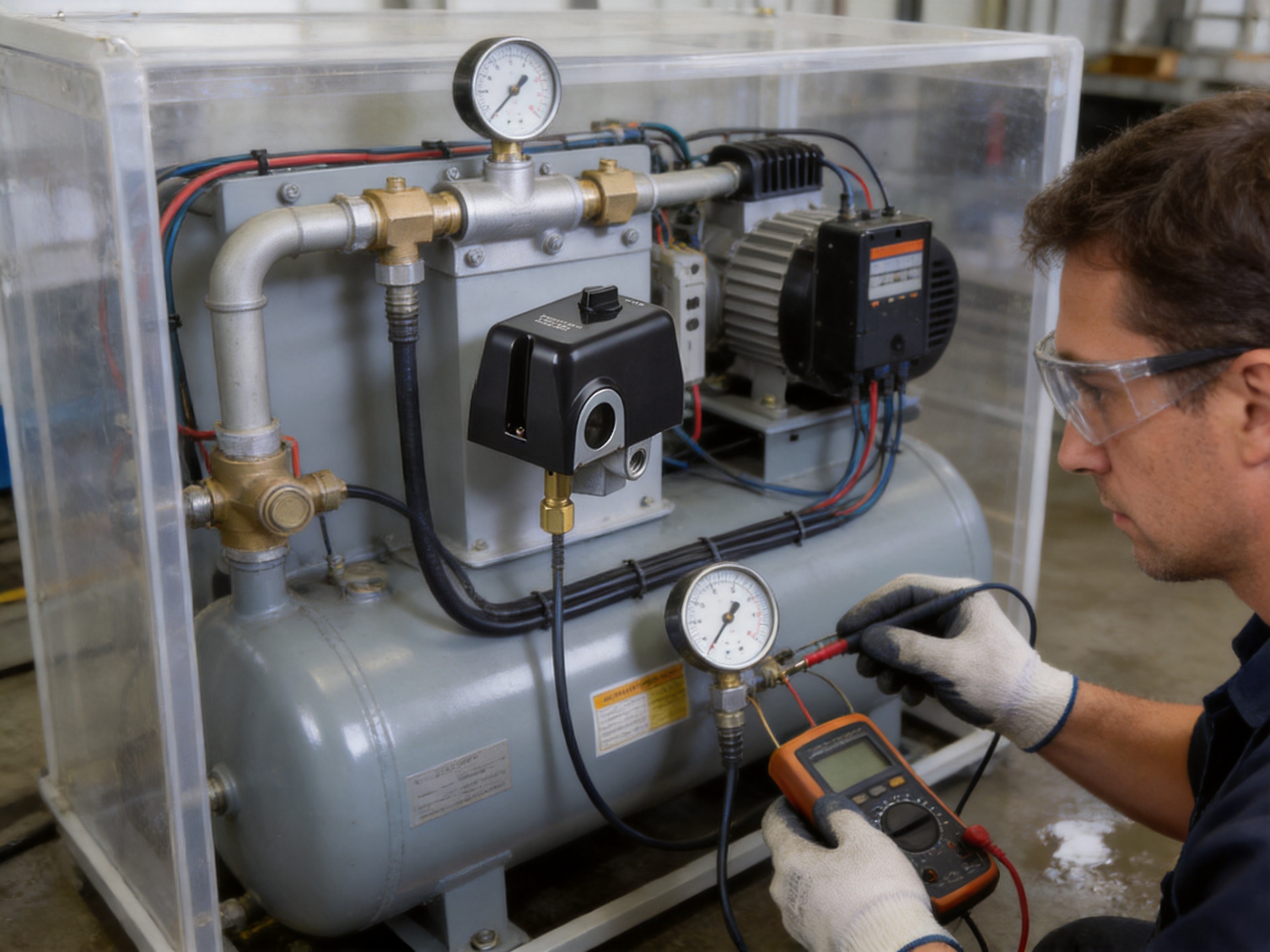
Routine inspection helps maintain reliable operation. Operators should periodically check for air leaks, damaged wiring, loose terminals, corrosion, abnormal compressor cycling, and physical damage to the pressure-switch housing.
If the compressor does not start when pressure falls below the cut-in point, check the power supply, wiring, motor starter, electrical contacts, pressure connection, and sensing mechanism. A blocked pressure passage or incorrect connection can prevent the switch from detecting actual system pressure.
If the compressor does not stop at the cut-out point, immediately disconnect power and release pressure safely. Possible causes include incorrect setting, welded electrical contacts, a blocked sensing passage, pressure leakage, or a defective mechanism. A compressor that fails to stop can create a serious overpressure hazard.
If the compressor starts and stops too frequently, inspect for air leaks, an undersized receiver, excessive air demand, an unsuitable pressure differential, or a malfunctioning check valve. The air-relief valve and discharge line should also be checked for correct operation.
If the switch operates inconsistently, inspect for moisture, vibration, contamination, damaged connections, or pressure fluctuations. The switch should not be opened or modified while connected to power or pressurized equipment.
When replacement is necessary, use a switch with matching pressure, voltage, current, connection, frequency, and environmental characteristics. Installing a switch with a higher apparent pressure range or current rating does not automatically make it suitable for the system.
Distributors benefit from a product family that covers several pressure ranges and connection formats. A well-organized inventory can serve multiple compressor models without requiring a completely unrelated component for every application.
OEM customers benefit from the ability to request customized settings and connections. This can reduce assembly modifications, support product differentiation, and create a more consistent user experience across a compressor range.
International customers may also value the supplier’s experience in export logistics, procurement planning, order tracking, and cross-border delivery. These capabilities are especially important for repeat orders, container shipments, and projects involving several pump or control products.
The one-year warranty provides a defined support period. Warranty terms, exclusions, required documentation, and replacement procedures should be confirmed in the commercial agreement. Customers should retain product labels, order information, installation records, and evidence of operating conditions if after-sales support is required.
A basic generic pressure switch may offer only a fixed connection, one standard pressure range, limited environmental resistance, and no integrated air-relief option. Such a product may be adequate for a simple indoor compressor, but it can become difficult to use when the equipment requires a special pressure cycle or piping arrangement.
The ERQ-4 Series offers a broader configuration concept. Its selectable pressure settings address more application types. Its male and female connection options accommodate different installation layouts. The optional one-way or four-way arrangement can simplify manifold integration. The delayed-closing air-relief valve supports compressor restart performance. Its water-resistant-oriented design addresses a common cause of premature control failure.
These features can create value beyond the initial purchase price. A correctly selected pressure switch may reduce adapter requirements, lower installation time, simplify spare-parts management, and reduce the frequency of moisture-related replacement. The actual advantage depends on the application, installation quality, and compliance with the product’s technical limits.
It is also important to compare products based on verified specifications rather than appearance or price alone. Buyers should examine pressure accuracy, electrical capacity, connection quality, operating temperature, protection degree, testing procedures, warranty, and technical support.
A pressure switch controls equipment containing stored energy. Compressed air can cause serious injury if pressure vessels, hoses, or fittings fail. Electrical circuits can cause shock, burns, or fire if incorrectly wired. The pressure switch must therefore be installed as part of a complete safety system.
The compressor should include an appropriate safety relief valve independent of the automatic pressure switch. The pressure switch is a control component and should not be considered the sole protection against overpressure.
The receiver tank should have a valid pressure rating and should be inspected according to local regulations. Hoses, valves, fittings, and pneumatic tools must be rated for the intended pressure. Operators should never bypass the pressure switch, safety valve, motor protection, or other protective devices.
Electrical installation should follow local codes and the compressor manufacturer’s wiring instructions. Grounding, overcurrent protection, isolation, and enclosure requirements must be addressed by a qualified person.
Before selecting the product for a regulated market, buyers should confirm applicable certification requirements. Depending on the destination and application, requirements may relate to electrical safety, electromagnetic compatibility, machinery safety, pressure equipment, materials, or environmental protection.
Before placing an order, the buyer should provide the following information:
• Required cut-in and cut-out pressure.
• Compressor motor voltage and phase.
• Running current and starting characteristics.
• Frequency of the electrical supply.
• Required hydraulic connection, including male or female thread.
• One-way or four-way connection preference.
• Air-relief valve requirement and tubing diameter.
• Ambient temperature and installation environment.
• Exposure to water, condensation, dust, chemicals, or outdoor conditions.
• Quantity, packaging, labeling, and documentation requirements.
• Any private-label housing or appearance requirements.
• Required inspection records or certification documents.
Purchasers should specifically clarify the voltage discrepancy between the product designation and the listed technical data. The final quotation and product label should clearly identify the approved electrical configuration. This step is essential for preventing incorrect shipments and unsafe installations.
Although a mechanical pressure switch is a relatively small component, its operating behavior can influence the lifecycle efficiency of an air compressor. Correct pressure control prevents unnecessary continuous running and can reduce energy waste caused by incorrect operating cycles.
The air-relief function may reduce mechanical stress during starts, potentially extending the useful life of the compressor motor and related components. Durable construction and resistance to moisture may reduce replacement frequency in demanding environments.
Longer service life can reduce material consumption, packaging waste, transportation requirements, and maintenance interruptions. These benefits depend on correct product selection, preventive maintenance, and responsible disposal at the end of service.
For industrial customers, the pressure switch can form part of a broader energy-management strategy. Leak detection, receiver sizing, variable-speed control, compressor sequencing, and correct pressure settings usually have a greater effect on total system efficiency, but dependable pressure switching remains an important foundation.
The primary use is automatic pressure control for air compressors. It starts the compressor when system pressure falls to the selected cut-in point and stops the compressor when pressure reaches the selected cut-out point.
The listed range extends from a minimum cut-in pressure of 20 psi to a maximum cut-out pressure of 175 psi. Available pressure settings include 20–50 psi, 30–60 psi, 40–70 psi, 50–80 psi, 95–125 psi, and 135–175 psi.
It is designed to provide water-resistant or impermeable-to-water protection against water ingress. However, the listed IP20 protection degree does not indicate protection against immersion or high-pressure water jets. Proper shielding and installation are still required.
The product designation refers to 110V–240V, while the technical information lists 380V. Buyers must confirm the exact model variation, voltage, phase, current, and wiring configuration before ordering. The final electrical rating should be verified from the product label and technical documentation.
The listed rated current is 12A. The actual motor application must remain within the approved electrical limits, including starting-current requirements. A contactor or motor starter may be needed for larger motors.
An air-relief valve with a delayed closing system is available as a product feature or option. Tubing options include 6 mm and 1/4-inch diameters. The valve should be correctly connected with the compressor discharge system and check valve.
The listed options include 1/4-inch male and female connections. One-way and four-way screw configurations can also be selected according to the installation layout.
Customized pressure settings are available according to customer requirements. The desired cut-in and cut-out values should be confirmed before production and must remain within the safe operating limits of the complete compressor system.
The listed maximum working temperature is 40°C. Ambient heat, motor heat, enclosure temperature, and direct sunlight should be considered when selecting the installation location.
No. A pressure switch is an automatic control device. The compressor system should also have an independent safety relief valve and other protective devices required by applicable regulations and equipment design.
Potential applications include industrial workshops, automotive repair shops, agricultural facilities, construction equipment, pneumatic machinery, service stations, and compressor manufacturing. Suitability depends on the verified pressure, electrical, temperature, and environmental requirements.
The supplied product information states a one-year warranty. Specific warranty conditions, exclusions, and service procedures should be confirmed with the supplier before purchase.
Buyers should provide the required pressure cycle, voltage, phase, current, frequency, connection type, air-relief requirement, working temperature, and environmental conditions. They should also confirm the final technical drawing, product label, and wiring information before installation.
The ERQ-4 Series pressure switch is a practical mechanical controller for air compressor systems requiring automatic pressure regulation, flexible configuration, and improved resistance to moisture-related conditions. Its selectable pressure ranges, 12A rating, 1/4-inch connection options, one-way or four-way configurations, and available delayed-closing air-relief valve make it adaptable to a broad range of compressor designs.
Its competitive value comes from combining pressure control with application-oriented options. Instead of relying on a single generic configuration, buyers can request a pressure setting, connection format, valve arrangement, or housing requirement that better matches the intended equipment. This can simplify integration and support more consistent manufacturing for distributors and OEM customers.
The manufacturing background of Taizhou Edwin Electric Co., Ltd. adds further value. Since its establishment in 2008, the company has focused on research and development, mass production, global export, and a broad range of pump and water-system products. Its experience with motors, hydraulic equipment, intelligent pumping, and international order fulfillment provides a strong foundation for supplying pressure-control components to industrial customers.
For the best results, the pressure switch must be selected and installed according to verified technical data. In particular, the voltage information should be confirmed because the supplied product description references both 110V–240V and 380V. The switch should also be protected from conditions beyond its stated IP20 rating, and it should be used together with an independent safety relief valve and appropriate motor protection.
When correctly specified and maintained, the ERQ-4 Series can provide dependable automatic compressor operation, easier equipment integration, and useful lifecycle value in workshops, industrial systems, agricultural facilities, and other compressed-air applications.
1. Product technical information for the ERQ-4 Series mechanical pressure controller, including pressure settings, electrical ratings, connection options, temperature limits, and protection degree.
2. General principles of compressed-air system design, receiver-tank operation, pressure regulation, and compressor unloading.
3. Industrial guidance on electrical motor control, pressure-switch installation, overcurrent protection, and safe isolation procedures.
4. General ingress-protection classification principles for electrical enclosures and control components.
5. Manufacturer information concerning research and development, mass production, pump manufacturing, global export, and customer customization services.
6. Standard maintenance practices for air compressors, pneumatic equipment, pressure vessels, check valves, and air-relief systems.
edwina@edwin-pump.com
+86-13586290903 (WhatsApp)
Xuri Gongliang Cutting Tool Entrepreneurship Park, Wenqiao Town, Wenling City, Taizhou City, Zhejiang Province, China

High Performance Smart Pump Factory


 English