edwina@edwin-pump.com

View All Products
en
Air compressors depend on accurate, repeatable, and dependable pressure control. Without a suitable pressure switch, a compressor may run continuously, start too frequently, exceed its intended pressure, or fail to provide enough compressed air for connected equipment. The ERQ-4 Series 12A pressure switch is designed to address these control requirements in air compressor systems used in workshops, industrial facilities, automotive repair operations, and other demanding working environments.
With selectable pressure settings from 20 to 175 psi, a nominal current rating of 12A, 50/60Hz frequency compatibility, optional hydraulic connections, and an air-relief valve with a delayed-closing system, the ERQ-4 Series offers a practical combination of pressure management, electrical versatility, installation flexibility, and service convenience. Its water-resistant design is intended to improve reliability where moisture exposure is common, while its compact mechanical control structure supports straightforward integration into many compressor assemblies.
This article examines the operating principle, technical characteristics, application value, configuration options, manufacturing strengths, installation considerations, maintenance requirements, and competitive advantages of the ERQ-4 Series pressure switch. It also explains an important point for buyers: electrical ratings, protection classifications, and pressure settings must be confirmed against the final configuration before installation.
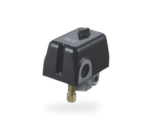
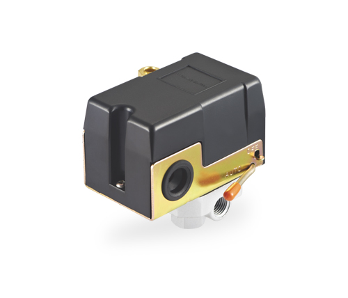
ERQ-4 Series 12A 110V to 240V Impermeable to Water Pressure Switch Used in Air Compressors
A pressure switch is one of the most important control components in a compressed-air system. It monitors pressure in the receiver tank or connected air line and automatically opens or closes an electrical circuit according to preset pressure limits. In a typical compressor application, the switch turns the motor on when system pressure falls to the cut-in point and turns the motor off when pressure reaches the cut-out point.
This automatic operating cycle prevents the compressor from running unnecessarily. It also helps maintain a usable air reserve for tools, machinery, pneumatic controls, and production equipment. By controlling the start and stop sequence, the pressure switch contributes to energy efficiency, motor protection, operational convenience, and consistent air availability.
For example, if a pressure switch is set to start at 30 psi and stop at 60 psi, the compressor begins operating when pressure drops below approximately 30 psi. It continues compressing air until the system reaches approximately 60 psi, at which point the electrical circuit opens and the motor stops. When the pressure falls again during use, the cycle repeats.
The ERQ-4 Series is intended for this type of automatic control. Its adjustable or customized setting options allow the switch to be matched to different compressor requirements. The available pressure-setting ranges include 20-50 psi, 30-60 psi, 40-70 psi, 50-80 psi, 95-125 psi, and 135-175 psi. These options cover both relatively low-pressure and higher-pressure applications, although the final setting should always remain within the safe working limits of the compressor, tank, hoses, valves, and connected equipment.
The ERQ-4 Series is a mechanical pressure controller developed for air compressor systems. It combines a pressure-sensing mechanism with an electrical switching assembly inside a compact control housing. When air pressure changes, the internal mechanism responds to the pressure difference and changes the state of the electrical contacts.
The product is identified as a 12A pressure switch and is described for use with electrical systems in the 110V to 240V range. The available technical information also lists a rated voltage of 380V. Because these values can represent different configurations, product versions, or application conditions, purchasers should confirm the correct voltage and wiring arrangement with the supplier before ordering. This confirmation is especially important when the switch will be used in a three-phase installation or with a motor whose starting current is considerably higher than its running current.
The pressure switch is designed to support reliable operation in environments where contact with moisture may occur. However, the listed protection degree is IP20. IP20 generally indicates protection against solid objects larger than 12.5 millimeters but does not indicate protection against water ingress. Therefore, the product’s stated water-resistant or impermeable design should not be interpreted as permission to expose the complete electrical enclosure to spray, immersion, or direct streams of water. Proper installation in a protected location remains essential.
| Parameter | Available Specification | Application Significance |
|---|---|---|
| Product series | ERQ-4 Series | Mechanical pressure control for air compressors |
| Pressure range | 20-175 psi overall range | Supports different compressor control requirements |
| Pressure settings | 20-50, 30-60, 40-70, 50-80, 95-125, and 135-175 psi | Provides selectable cut-in and cut-out combinations |
| Rated current | 12A | Suitable for compatible compressor control circuits |
| Voltage information | 110V-240V described; 380V also listed | Final voltage configuration must be verified before installation |
| Frequency | 50/60Hz | Compatible with common power frequencies |
| Maximum working temperature | 40°C | Installation environment should remain within the stated limit |
| Protection degree | IP20 | Requires installation away from direct water exposure |
| Hydraulic connection | 1/4-inch male or female options | Allows adaptation to different compressor plumbing arrangements |
| Air-relief valve | Delayed-closing system; 6 mm or 1/4-inch pipe options | Helps relieve residual pressure during motor restart |
| Warranty | One year | Provides defined after-sales support for the standard product |
The main operating principle of the ERQ-4 Series is mechanical pressure detection. A pressure-sensitive internal element reacts to the air pressure transmitted from the compressor tank or air line. The pressure force is balanced against a spring or adjustment mechanism. When pressure reaches the selected cut-in or cut-out point, the mechanism changes the position of the electrical contacts.
This method has several practical benefits. Mechanical pressure control does not require a separate electronic pressure sensor, software platform, or external controller for basic start-and-stop operation. The system is comparatively easy to understand, install, test, and replace. In workshops and service environments, technicians can often diagnose the pressure switch using visual inspection, pressure readings, continuity testing, and an evaluation of the compressor’s start and stop behavior.
The difference between the cut-in pressure and cut-out pressure is commonly called the differential or pressure band. A suitable differential prevents the compressor from starting and stopping too frequently. Excessively narrow settings may lead to rapid cycling, increasing motor wear, contact wear, and thermal stress. Excessively wide settings may create pressure fluctuations that are unsuitable for certain pneumatic tools or production processes. The available ERQ-4 Series settings provide a selection of pressure bands for different operating requirements.
For a small workshop compressor, a 30-60 psi or 40-70 psi setting may be suitable if the connected equipment operates at relatively low pressure. A system requiring a higher reserve may use a 95-125 psi setting. Applications with higher pressure requirements may consider the 135-175 psi range, provided that every component in the system is rated for the selected pressure.
Pressure settings should not be selected solely according to the desired output of a tool. The complete system must be considered, including compressor displacement, tank capacity, motor power, pressure relief valve rating, receiver certification, hose rating, regulator capacity, and the pressure requirements of downstream equipment.
One important advantage of the ERQ-4 Series is the availability of several factory pressure-setting ranges. Some basic pressure switches are supplied with only one fixed configuration or provide limited adjustment. By contrast, the ERQ-4 Series can be specified for different cut-in and cut-out requirements, helping distributors and equipment manufacturers reduce the need to redesign the entire control system for each compressor model.
The setting options also support different market requirements. A low-pressure workshop compressor, a medium-duty service compressor, and a higher-pressure industrial unit may all require different control points. Offering multiple ranges allows one product family to address more applications while simplifying procurement and replacement planning.
The stated 110V-240V compatibility is useful for many common electrical systems. The 50/60Hz specification further supports international use in markets operating on either of the two common commercial frequencies. This flexibility is valuable for exporters, original equipment manufacturers, service distributors, and users who operate equipment in regions with different electrical standards.
The listed 380V rating indicates that a related configuration may be available for higher-voltage or three-phase systems. Because the product information includes both 110V-240V and 380V references, the exact model code, contact arrangement, phase configuration, and wiring diagram should be confirmed before purchase. This verification is a strength of responsible product selection, not a weakness of the design: a pressure switch must always be matched to the actual motor circuit rather than selected only by its appearance or general series name.
The optional air-relief valve with a delayed-closing system is another useful feature. When a compressor stops, compressed air may remain trapped in the discharge pipe between the compressor head and the check valve. If this residual pressure is not released, the motor may have difficulty starting against the trapped load. This condition can cause high starting current, motor humming, thermal overload, nuisance tripping, or premature wear.
An air-relief valve helps reduce this residual pressure. The delayed-closing design allows pressure to be released during the stopping and restarting sequence while preventing unnecessary air loss during normal operation. The availability of 6-millimeter or 1/4-inch pipe options allows the relief connection to be adapted to different compressor layouts.
The ERQ-4 Series can be supplied with 1/4-inch male or female hydraulic connections. One-way and four-way screw configurations are also listed. These options allow the pressure switch to be installed on different tanks, manifolds, or pipe arrangements without requiring extensive modification.
Connection flexibility can reduce installation time and help distributors serve a broader range of compressor brands and designs. It also supports replacement work, where the existing plumbing arrangement may not match a single standardized connection. The correct thread type, sealing method, orientation, and pressure rating must still be verified for each installation.
The product description emphasizes an impermeable-to-water design. In practical terms, this feature is intended to improve resistance to moisture-related deterioration in environments such as workshops, garages, agricultural service areas, and industrial rooms where humidity or occasional splashing may occur.
Compared with a basic controller that has little attention to environmental sealing, a better-protected design can help reduce the risk of moisture reaching sensitive mechanical and electrical components. It may also contribute to longer service life when the switch is installed correctly and protected from direct water exposure.
Nevertheless, the listed IP20 classification should be respected. The switch should be mounted in a dry, ventilated, and protected position. If the compressor is used outdoors, near washdown equipment, or in a location exposed to spray, the complete control assembly may require an additional protective enclosure with an appropriate ingress-protection rating.
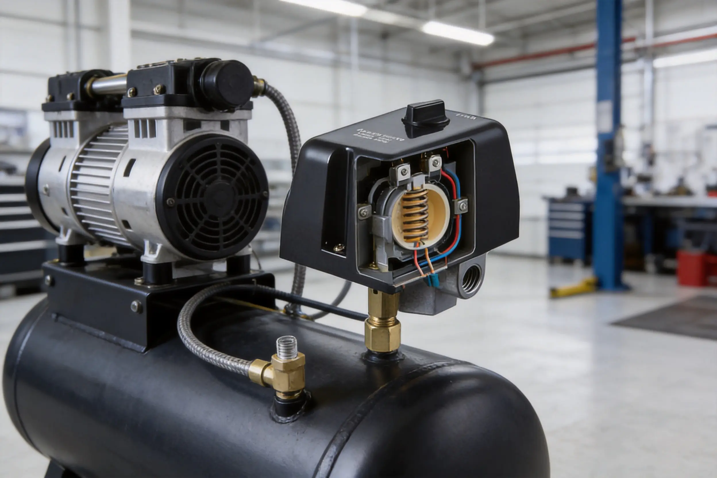
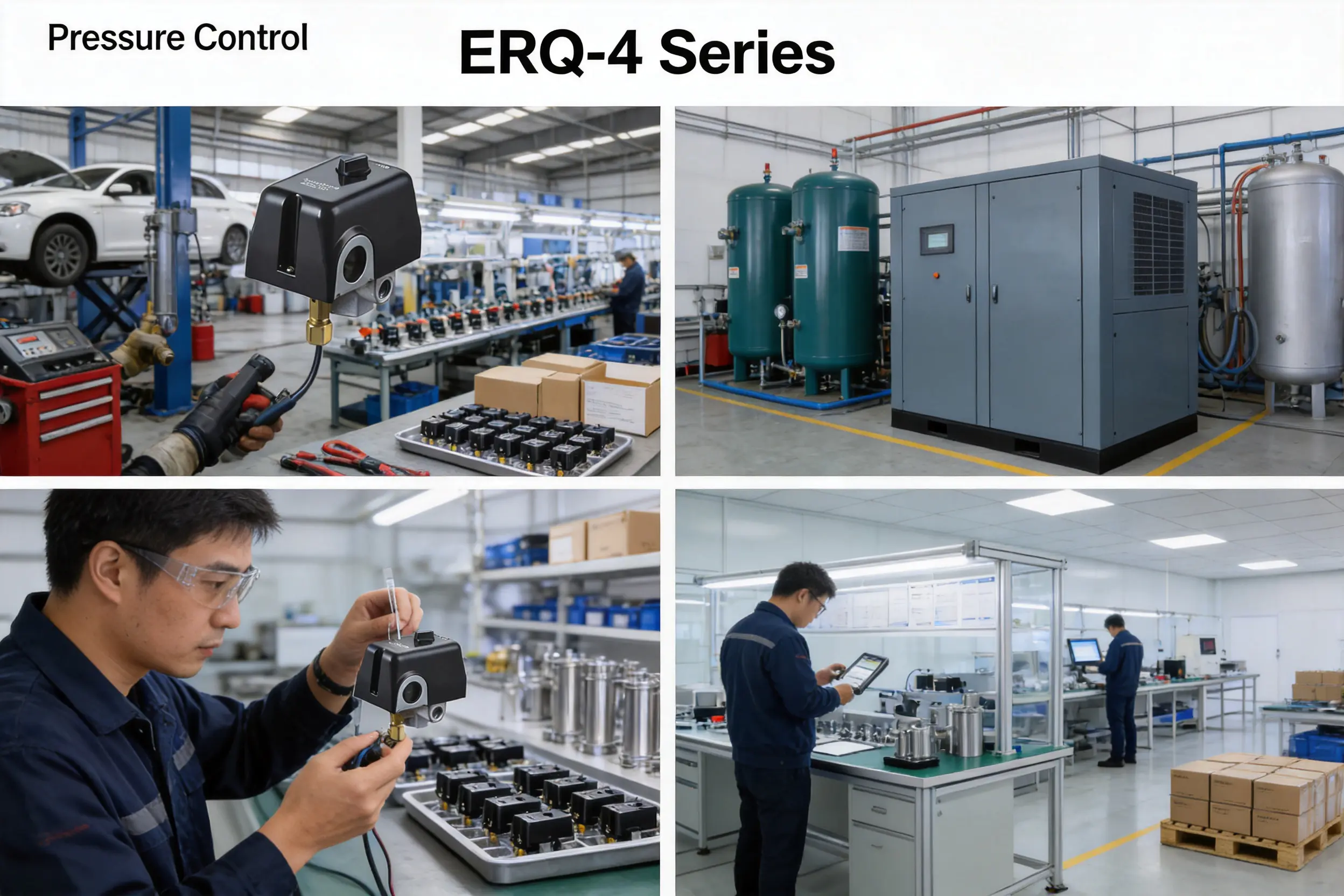
Industrial workshops often use compressed air for impact tools, spray equipment, pneumatic cylinders, cleaning operations, and automated machinery. In these environments, a pressure switch must perform repeated operating cycles and maintain stable control under changing demand.
The ERQ-4 Series can be selected according to the pressure requirements of the workshop system. Its mechanical operating principle is suitable for facilities that prefer simple, serviceable control components. The availability of customized pressure settings can also help equipment builders match the switch to the working pressure of a particular compressor package.
Automotive repair shops may operate tire inflators, air ratchets, spray guns, lifts, cleaning tools, and other pneumatic devices. Demand can vary sharply during the day. The compressor may remain idle for several minutes and then run frequently when multiple tools are used at once.
A correctly selected pressure switch helps the compressor respond automatically to this variable demand. The air-relief valve can support more reliable motor restarting, particularly when the compressor is switched on and off repeatedly. Since automotive service areas may contain oil vapor, dust, condensation, and occasional splashing, careful installation and routine inspection are important.
Commercial equipment manufacturers may integrate the ERQ-4 Series into compact compressor packages, air treatment units, service machines, and specialty pneumatic systems. The connection and pressure-setting options can simplify product configuration across several equipment models.
For original equipment manufacturers, a standardized pressure-switch family can reduce design complexity. Different versions may be specified for different pressure bands or electrical supplies while preserving a similar installation concept. This can help streamline assembly instructions, technician training, spare-parts management, and purchasing schedules.
Compressed air systems used around farms, maintenance buildings, pump rooms, and utility installations may face dust, humidity, and temperature variation. A pressure switch with a moisture-conscious design may provide better environmental resilience than a poorly protected alternative, provided that the actual installation meets the product’s protection limitations.
Users should avoid installing the switch directly beneath a leaking pipe, beside an open drain, or in a location where condensation accumulates. A short protective air tube or suitable mounting arrangement can help separate the pressure switch from vibration and heat sources.
The product is manufactured by an integrated electrical equipment company established in 2008. The organization combines independent research and development, mass production, and global export capabilities. This integrated structure is significant because pressure switches require more than a simple assembly operation. Consistent performance depends on the compatibility of pressure-sensing components, springs, electrical contacts, molded or formed housing parts, connection fittings, and final calibration.
Independent research and development allows the manufacturer to adapt pressure ranges, hydraulic connections, relief-valve arrangements, crust or housing requirements, and customer-specific settings. These capabilities are particularly valuable for compressor manufacturers that need a pressure switch adapted to a particular tank layout or motor-control design.
Mass-production capability supports repeatability. When a pressure switch is used in a large equipment program, buyers need consistent dimensions, thread forms, contact behavior, pressure settings, and packaging. A structured production system can help maintain these characteristics across repeated orders. It can also improve the availability of replacement products for distributors and end users.
The company’s wider product experience includes deep well pumps, submersible pumps, domestic booster pumps, circulation pumps, solar water pumps, intelligent booster pumps, and related water-treatment peripheral products. Although an air compressor pressure switch is different from a water pump, experience in fluid-handling equipment can contribute to an understanding of pressure control, sealing, hydraulic connections, motor operation, and application-specific durability.
The manufacturer also serves international customers through dedicated import, export, procurement, order-tracking, and cross-border delivery resources. For industrial buyers, this broader service structure can be as important as the component itself. A reliable supply process helps customers manage technical confirmation, sample approval, production planning, shipping documents, and after-sales communication.
Customization is one of the stated capabilities of the ERQ-4 Series. Customers may request different housing treatments, hydraulic connections, pressure settings, and air-relief-valve arrangements. Such options indicate that the product is not limited to one rigid configuration.
In a professional development process, customization should begin with a technical review. The customer provides information about the compressor motor voltage, phase, running current, starting characteristics, tank pressure, desired cut-in and cut-out points, connection thread, ambient temperature, and installation environment. The manufacturer can then recommend a suitable configuration, prototype if necessary, and confirm the product before mass production.
For a mechanical pressure switch, manufacturing consistency is closely connected to control accuracy and service life. The pressure-sensing mechanism must move smoothly, the adjustment system must maintain its selected position, and the electrical contacts must switch cleanly. Threaded connections must be formed accurately to prevent leakage or difficult installation.
A capable factory should therefore control incoming materials, component dimensions, assembly conditions, calibration, electrical continuity, and visual quality. Batch records and inspection procedures help identify deviations before products are shipped. These practices are especially important when the switch is customized for a specific pressure band or electrical arrangement.
The manufacturer’s broader business structure includes procurement planning, order tracking, cross-border delivery, and foreign-trade services. This one-stop approach may reduce the administrative burden for overseas purchasers. Buyers can coordinate technical specifications, quantities, packaging, delivery timing, and documentation through a professional export team rather than managing each activity separately.
For distributors, this can improve stock planning and support private-label or customized purchasing programs. For equipment manufacturers, it can make it easier to combine pressure switches with pumps, motors, valves, or other related products from one supply network, subject to technical compatibility and commercial agreement.
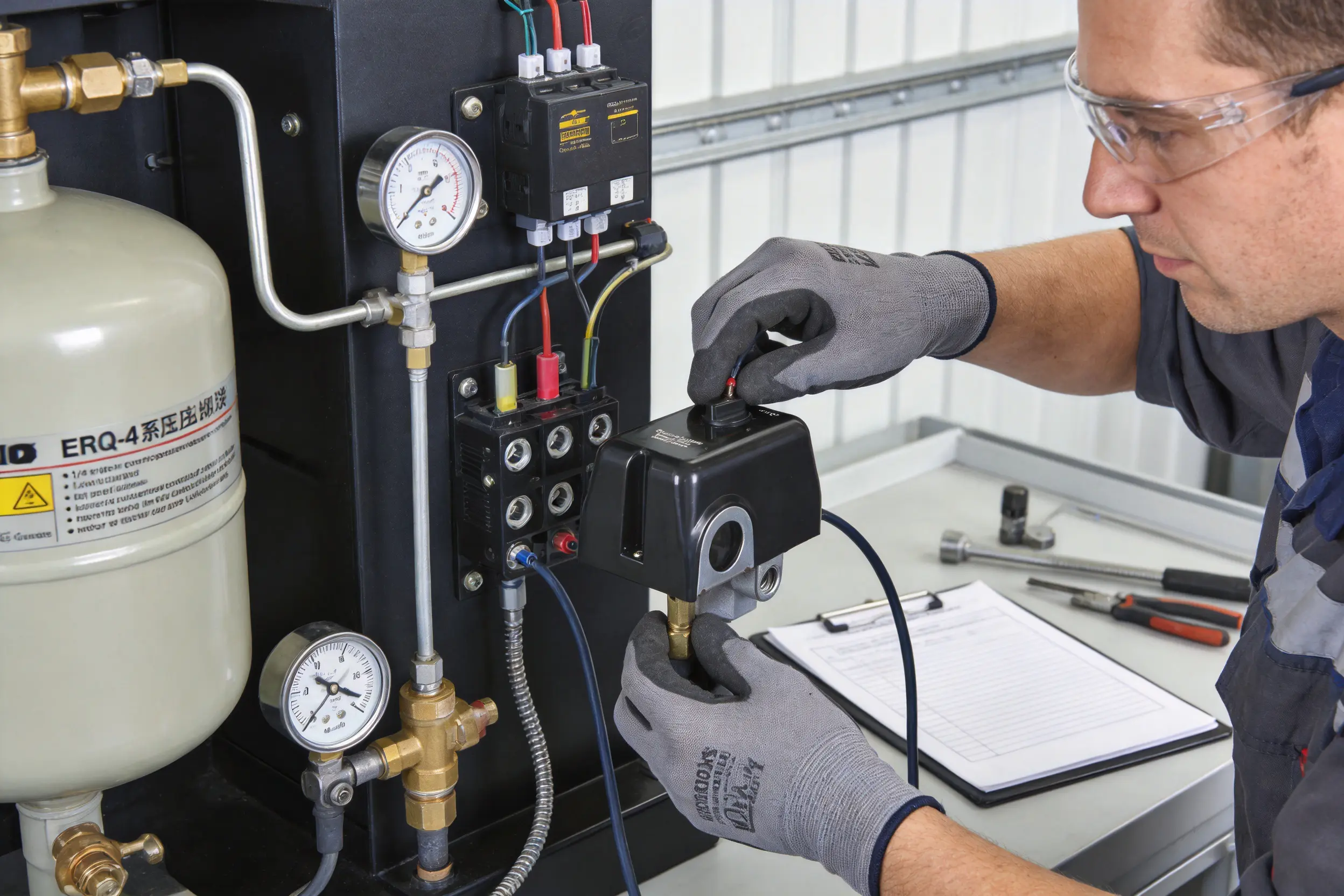
Installation should be performed by a qualified technician familiar with pressure systems and electrical motor controls. Before work begins, disconnect the compressor from the power supply, release stored air pressure where appropriate, and follow all applicable electrical and workplace safety procedures.
Before installing the switch, confirm the compressor’s rated voltage, phase, frequency, motor current, pressure range, tank rating, connection thread, and control-circuit design. The pressure switch must be used within its electrical and mechanical limits. If the motor’s full-load current approaches the switch rating, or if the motor has a high starting current, an external contactor may be required.
Choose the cut-in and cut-out values according to the compressor manufacturer’s instructions and the pressure requirements of the air system. Do not exceed the maximum working pressure of the receiver, pipework, relief valve, regulator, hose, or connected equipment.
The switch should not be adjusted casually while the compressor is operating. If the product is supplied with a factory-customized setting, the adjustment should be protected from unauthorized changes. Any revised pressure setting should be documented and checked with a calibrated pressure gauge.
Check whether the installation requires a 1/4-inch male or female connection and whether the one-way or four-way configuration is appropriate. Use a compatible sealing method suitable for compressed air. Avoid excessive thread-sealing material, since loose fragments may enter the pressure passage or interfere with the check valve.
The switch should be installed in a position that avoids excessive vibration. If vibration is unavoidable, a suitable flexible connection may reduce mechanical stress. The pressure port should not be obstructed, and the pressure path should be kept free from dirt, oil sludge, and condensation.
If the compressor uses the air-relief function, connect the selected 6-millimeter or 1/4-inch tube correctly. The tube should be routed without sharp kinks and should not be exposed to excessive heat. The relief outlet must not be blocked, crushed, or directed toward a person.
After installation, observe the stopping and restarting sequence. When the motor stops, the relief valve should operate as intended. When the compressor restarts, the valve should close after the designed delay. Abnormal hissing, continuous air loss, or difficult motor starting may indicate incorrect tubing, a leaking check valve, contamination, or a damaged relief mechanism.
Follow the approved wiring diagram for the specific voltage and phase configuration. Use conductors with suitable insulation, current capacity, and temperature rating. All terminals should be tightened securely without damaging the contact components.
Electrical work must comply with local regulations. The equipment should have appropriate grounding, overcurrent protection, motor overload protection, and emergency isolation. A pressure switch is not a substitute for a correctly sized circuit breaker, motor protector, or pressure relief valve.
After installation, inspect the hydraulic and electrical connections before applying power. Start the compressor under controlled conditions and observe the pressure gauge, motor current, switching behavior, and air-relief function. Confirm that the compressor stops at the intended cut-out pressure and restarts at the intended cut-in pressure.
Use a calibrated reference gauge when accuracy is important. If the switch operates significantly above or below the expected setting, stop the equipment and investigate before placing the compressor into normal service.
Although the ERQ-4 Series is designed for dependable service, regular inspection helps prevent unexpected downtime. Maintenance frequency depends on operating cycles, air quality, humidity, vibration, and the cleanliness of the installation environment.
Inspect the housing for cracks, deformation, loose covers, corrosion, or signs of water exposure. Check the hydraulic connection for air leakage and examine the relief tube for cuts, kinks, or blockage. Confirm that electrical terminals remain tight and that no insulation has darkened from overheating.
The surrounding compressor should also be inspected. Excessive vibration, oil carryover, tank corrosion, blocked ventilation, and a malfunctioning check valve may create conditions that appear to be pressure-switch problems.
If the compressor does not start when pressure falls below the cut-in point, first confirm that power is available and that the emergency stop or overload protector has not opened. Check the pressure-switch contacts for continuity and inspect the wiring.
Residual pressure in the discharge line may also prevent the motor from starting. Inspect the air-relief valve and check valve. If the relief valve does not release trapped air after shutdown, the motor may be starting under excessive load.
If the compressor continues running after reaching the expected cut-out pressure, check the pressure gauge against a calibrated instrument. Inspect the pressure-sensing passage for blockage and verify that the internal mechanism is not damaged or contaminated. The electrical contacts may be welded or stuck if the switch has been overloaded.
Do not allow the compressor to continue operating without a functioning independent safety relief valve. A pressure switch controls normal operation, but the relief valve provides an essential last line of protection against overpressure.
Frequent starting and stopping may result from an unsuitable pressure differential, an undersized receiver tank, a significant air leak, a faulty check valve, or a demand pattern beyond the compressor’s capacity. Replacing the pressure switch alone may not solve the underlying problem.
Check all air connections with an approved leak-detection method. Review the cut-in and cut-out settings and ensure that the compressor has sufficient tank volume for the connected tools. If the pressure band has been customized, confirm that it matches the intended application.
If moisture is found inside or around the pressure switch, identify the source immediately. Condensation may come from compressed air, a leaking pipe, outdoor exposure, washdown operations, or poor ventilation. The switch should be relocated or protected if the installation environment exceeds the practical limitations of the IP20 enclosure.
Water-resistant construction can improve durability, but it cannot compensate for direct immersion or continuous spray. In wet locations, use an appropriate protective enclosure and ensure that cable entries, conduit fittings, and mounting surfaces also provide adequate protection.
The ERQ-4 Series should be compared with alternatives according to the needs of the compressor rather than by price alone. Different systems may use mechanical pressure switches, electronic pressure transducers, programmable controllers, or a pressure sensor connected to a motor drive.
A basic fixed-setting pressure switch may be adequate for a simple compressor with one operating condition. However, it may provide limited flexibility when the same equipment family is sold into different markets or when customers require different pressure bands.
The ERQ-4 Series offers several preset ranges and customized settings, making it more adaptable for manufacturers and replacement markets. Its connection options can also reduce the need for additional adapters.
Electronic controllers can offer digital displays, programmable functions, data logging, alarms, and advanced system integration. These features may be valuable in sophisticated installations. However, they can also increase cost, wiring complexity, sensitivity to electrical disturbances, and dependence on electronic components.
The mechanical ERQ-4 Series is attractive when the main requirement is dependable automatic start-and-stop control. It can be easier to service in locations where technicians prefer mechanical components and where advanced data functions are unnecessary.
A separate pressure sensor and contactor arrangement may provide more control flexibility and greater motor-switching capacity. It may be preferred for large motors, high starting currents, central control panels, or systems requiring multiple interlocks.
The ERQ-4 Series can provide a more compact and economical solution for compatible compressor systems. When the motor load exceeds the direct-switching capability, the pressure switch can potentially be used as a control signal for a contactor, subject to the approved wiring design and manufacturer guidance.
The ERQ-4 Series combines several features that are not always found together in an entry-level pressure switch: multiple pressure ranges, 50/60Hz compatibility, connection choices, an air-relief option, customization support, and a design intended to improve resistance to moisture exposure. These characteristics can provide better application flexibility than a single-purpose alternative.
Its competitive value also comes from manufacturing support. A supplier capable of research and development, mass production, customization, export coordination, and after-sales service can offer more than a standalone component reseller. Buyers may receive better assistance with specification matching, production planning, and long-term replacement supply.
Before ordering the ERQ-4 Series, buyers should prepare a complete technical specification. This reduces the risk of receiving a switch with an unsuitable voltage, pressure range, thread type, or relief-valve arrangement.
| Selection Item | Information to Confirm | Why It Matters |
|---|---|---|
| Compressor type | Reciprocating, rotary, portable, stationary, or specialty compressor | Different machines have different pressure and cycling characteristics |
| Motor supply | Voltage, phase, frequency, and control method | Prevents incorrect electrical configuration |
| Motor current | Running current and starting current | Determines whether direct switching or a contactor is required |
| Cut-in pressure | Required start pressure | Controls when the compressor begins refilling the tank |
| Cut-out pressure | Required stop pressure | Controls the maximum normal operating pressure |
| Connection | 1/4-inch male or female; one-way or four-way | Ensures mechanical compatibility |
| Relief valve | Required or not required; 6 mm or 1/4-inch tube | Supports reliable motor restarting |
| Environment | Temperature, humidity, dust, vibration, and water exposure | Determines whether additional protection is necessary |
| Customization | Housing, pressure setting, connection, and packaging requirements | Supports OEM and distributor programs |
| Documentation | Wiring diagram, setting confirmation, inspection records, and warranty terms | Supports installation and after-sales service |
Purchasers should also confirm the meaning of all ratings on the final product label. The available information includes both 110V-240V and 380V references. The correct interpretation may depend on the precise variant, contact arrangement, or market configuration. Written confirmation is recommended for every new application.
Original equipment manufacturers need components that are technically suitable, repeatable in production, and available over the expected product life. The ERQ-4 Series can support these requirements through its configurable pressure settings and connection options.
An OEM may use one standard pressure-switch family across several compressor models. A low-pressure model can use one factory setting, while a higher-pressure model uses another. Different connection styles can be specified for different tank or manifold layouts. This approach reduces engineering duplication and may simplify training for assembly and service personnel.
Distributors can benefit from stocking a product with broad application coverage. The available pressure ranges allow a distributor to serve multiple customer groups, while the 12A electrical rating and common connection sizes make the product relevant to many small and medium compressor systems. Customized settings may also support regional market preferences or private-label programs.
Export customers may value the manufacturer’s ability to coordinate procurement, production, order tracking, delivery, and foreign-trade services. A single supplier relationship can simplify communication and reduce the risk of inconsistent technical information between component vendors.
Compressed air contains stored energy and can cause serious injury if a tank, hose, fitting, or valve fails. Electrical motors and circuits also present shock, arc-flash, and fire hazards. The pressure switch must therefore be treated as one part of a complete safety system.
Always use a correctly rated pressure relief valve. Never bypass the relief valve or set the pressure switch above the certified pressure rating of the receiver. Do not remove covers while power is connected. Before servicing, isolate electrical power, lock out the disconnect where required, and release stored pressure in accordance with the equipment manufacturer’s procedure.
Do not use the switch in an environment beyond its stated maximum working temperature of 40°C unless the manufacturer has approved a different configuration. Excessive heat can affect contact life, housing materials, pressure calibration, and insulation performance.
Protect the controller from direct water exposure even though the design is intended to provide improved resistance to moisture. The listed IP20 protection degree does not make the complete switch suitable for water jets or immersion. If the compressor is installed outdoors or in a washdown area, a suitably rated enclosure and cable-entry system should be used.
Only qualified personnel should change pressure settings or electrical connections. After any adjustment, the system must be tested at controlled pressure while monitoring the gauge and motor behavior. If the compressor shows abnormal noise, repeated overload trips, unstable pressure, or continuous air leakage, stop operation and investigate the cause.
A pressure switch may appear to be a small and simple product, but its reliability depends on the interaction of many details. The pressure mechanism must respond consistently. The spring must provide a stable force. The contacts must carry the intended load without excessive heating or welding. The housing must protect internal components from normal workshop conditions. The threads must fit correctly and seal reliably. The relief valve must open and close at the correct stage of the compressor cycle.
An integrated manufacturer can coordinate these details more effectively than a supplier that only performs final packaging. Research and development teams can evaluate new configurations. Production teams can standardize assembly. Quality personnel can inspect electrical and mechanical performance. Export and service teams can communicate technical information to international customers.
The manufacturer’s history of producing pumps and related fluid-control products provides a foundation in motor-driven equipment, fluid pressure, hydraulic connections, and application engineering. Its expansion into solar water pumps and intelligent booster pumps also reflects investment in new energy and intelligent technology. These capabilities support a broader understanding of how pressure, flow, motor control, and environmental conditions affect equipment performance.
For buyers, the practical benefit is a more complete supply relationship. Instead of purchasing a pressure switch without technical support, customers can discuss pressure settings, connection arrangements, electrical requirements, and intended applications with a factory that operates across several pump and fluid-equipment categories.
The primary purpose is to automatically start and stop an air compressor according to system pressure. It activates the compressor when pressure falls to the selected cut-in point and stops the compressor when pressure reaches the selected cut-out point.
The listed pressure-setting options are 20-50 psi, 30-60 psi, 40-70 psi, 50-80 psi, 95-125 psi, and 135-175 psi. Customized settings may also be available. The selected range must be compatible with the compressor, receiver, safety valve, and connected equipment.
The product description identifies compatibility with a 110V-240V range. However, the technical information also lists a 380V rated voltage. Customers should confirm the exact electrical configuration, phase, contact arrangement, and wiring diagram for the selected version before installation.
Not necessarily. The 12A rating must be compared with the motor’s running current, starting current, voltage, phase, and switching duty. Some motors require a contactor or an additional motor-protection device even when their running current appears to be within the nominal switch rating.
No. The listed protection degree is IP20, which does not indicate protection against water ingress. The water-resistant or impermeable design should be understood as an effort to improve durability in moisture-prone conditions, not as approval for immersion or direct water jets. The switch should be installed in a protected location.
The air-relief valve releases residual air pressure from the compressor discharge line after the motor stops. The delayed-closing system helps reduce the load on the motor during restarting. The available tube options are 6 millimeters and 1/4 inch.
The listed options include 1/4-inch male and female connections. One-way and four-way screw configurations are also available, depending on the required installation arrangement.
The listed maximum working temperature is 40°C. The compressor should be installed in a ventilated location away from excessive heat. If the application exceeds this temperature, the customer should request a technical review before use.
Yes. Customized pressure settings are listed among the product options. Customers should provide the required cut-in and cut-out pressures and obtain written confirmation before production or installation.
Check for air leaks, an undersized receiver, an unsuitable pressure differential, a faulty check valve, or excessive air demand. Verify the pressure switch setting with a calibrated gauge. Replacing the switch may not solve the problem if the underlying issue is in another part of the compressed-air system.
It may be used in an outdoor system only when it is installed inside a suitable protective enclosure and kept within its environmental limits. Because the listed enclosure classification is IP20, the complete switch should not be directly exposed to rain, spray, or condensation.
The product information states a one-year warranty. Buyers should confirm the warranty coverage, exclusions, claim procedure, and required installation conditions with the supplier before ordering.
It may be suitable if the pressure range, voltage, current, thread, contact arrangement, air-relief connection, physical dimensions, and environmental conditions match. A replacement should never be selected by appearance alone. Compare the original switch label and wiring with the proposed ERQ-4 Series configuration.
Its multiple pressure ranges, optional connections, customizable settings, 50/60Hz frequency compatibility, air-relief function, and factory support make it adaptable to different compressor designs. The manufacturer’s research, mass-production, export, and order-management capabilities further support OEM and distributor requirements.
The ERQ-4 Series 12A pressure switch is a practical mechanical controller for air compressor start-and-stop management. Its principal strengths are application flexibility, selectable pressure ranges, common electrical-frequency compatibility, optional hydraulic connections, an air-relief valve with delayed closing, and support for customized settings.
Compared with a basic fixed-setting controller, it can provide greater adaptability for different compressor models and replacement requirements. Compared with a fully electronic control system, it offers a simpler mechanical solution for applications that do not require digital monitoring, programming, or data communication. Its water-resistant design can contribute to better durability in moisture-prone working environments when the switch is installed with appropriate protection.
The product is supported by an integrated manufacturer with experience in research and development, mass production, global export, fluid-handling equipment, pumps, and intelligent water systems. This combination can benefit industrial customers seeking technical customization, stable production, coordinated logistics, and long-term supply support.
Correct specification remains essential. The listed electrical information should be verified for the exact model, especially where 110V-240V and 380V applications are both referenced. The IP20 classification must also be respected, and the switch should not be exposed to direct water or immersion. When properly selected, installed, adjusted, and maintained, the ERQ-4 Series can provide dependable pressure control for workshops, service operations, commercial equipment, and compatible industrial air compressor systems.
1. Product technical information for the ERQ-4 Series pressure switch, including pressure ranges, voltage, current, frequency, connection options, relief-valve options, temperature, and protection classification.
2. Manufacturer-provided product description and application notes for mechanical pressure controllers used in air compressors.
3. General principles of compressed-air receiver operation, pressure-switch cut-in and cut-out control, and compressor unloading systems.
4. General electrical safety practices for motor circuits, overload protection, grounding, isolation, and pressure-control equipment.
5. General guidance on ingress-protection classifications and the limitations of IP20 enclosures in wet environments.
6. General maintenance practices for air compressors, pressure vessels, check valves, relief valves, pneumatic tubing, and mechanical control switches.
edwina@edwin-pump.com
+86-13586290903 (WhatsApp)
Xuri Gongliang Cutting Tool Entrepreneurship Park, Wenqiao Town, Wenling City, Taizhou City, Zhejiang Province, China

High Performance Smart Pump Factory


 English