edwina@edwin-pump.com

View All Products
en
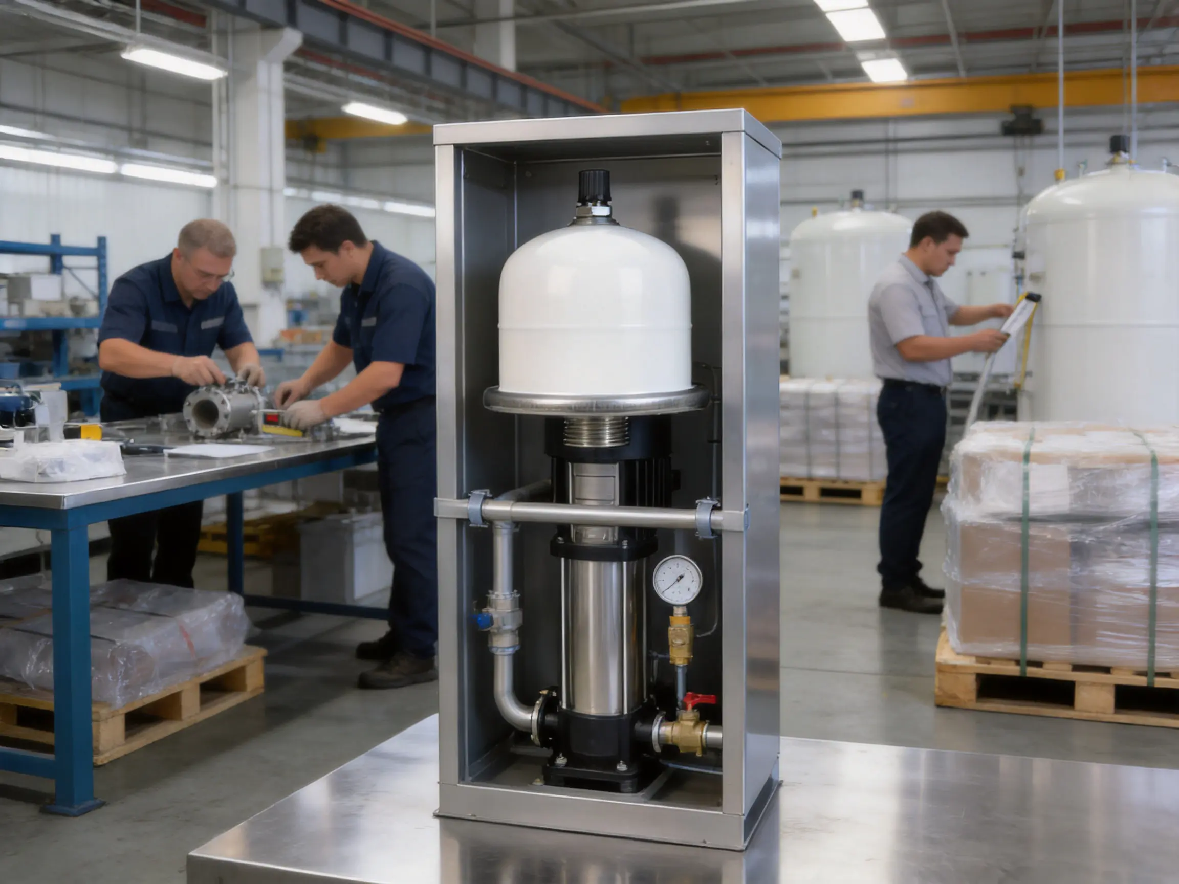
Modern heating installations, domestic water networks, booster systems, and industrial fluid applications all depend on stable pressure. When water is heated, cooled, accelerated, or stopped suddenly, its volume and flow conditions change. Without a suitable pressure-management device, these changes can cause pressure spikes, water hammer, pump cycling, noise, leakage, and premature wear on valves and pipework. The VT0.16 Series Stainless Steel Flange 8 Bar Fixed Membrane Expansion Pressure Tank is designed to address these challenges through compact construction, a fixed membrane, corrosion-resistant materials, and dependable pressure buffering.
This type of tank provides a controlled space in which water can expand and contract while the gas charge behind the membrane absorbs volume changes. By reducing the frequency and severity of pressure fluctuations, the tank helps a connected water or heating system operate more smoothly. It can also reduce unnecessary pump starts, support more consistent outlet pressure, and protect other components from repeated hydraulic stress.
The VT0.16 Series is especially suitable for heating systems and water supply networks that require a working temperature range from -20°C to +99°C and a maximum pressure rating of 8 bar. Its stainless steel flange and compact connection arrangement support practical installation where durability, hygiene, and space efficiency are important considerations.
The VT0.16 Series is a fixed membrane expansion pressure tank developed for pressure regulation and temporary water storage. The tank contains a water chamber and a gas-charged chamber separated by a permanent membrane. As water enters the tank, the membrane moves against the compressed gas. As system pressure falls, the stored water can return to the circuit, helping maintain a more stable operating condition.
The fixed membrane design is a key feature of the product. Unlike a service arrangement in which a replaceable bladder may be removed as a separate component, a fixed membrane is integrated into the tank structure. This creates a compact assembly with fewer service interfaces. It is particularly appropriate for applications in which the tank is selected, installed, and operated as a complete pressure-management unit.
The product information identifies the tank as a stainless steel flange model, while the wider product classification refers to pressure tanks and carbon steel pressure-tank categories. For final purchasing, users should confirm the exact vessel material, flange specification, membrane material, connection details, and approval documentation for the selected production batch. This confirmation is important because pressure-tank configurations can vary according to market, application, and customer requirements.
With a maximum pressure rating of 8 bar, the VT0.16 Series is intended for many residential, commercial, and light industrial systems. Its stated working temperature range of -20°C to +99°C allows use with cold-water services and a broad selection of heating applications. System designers must still verify that the actual fluid, operating temperature, pressure, and installation environment remain within the approved limits.

VT0.16 Series Stainless Steel Flange 8 Bar Fixed Membrane Expansion Pressure Tank
Water is often treated as incompressible in basic hydraulic calculations, but the total volume of water in a closed system changes when temperature and pressure change. A heating circuit illustrates this clearly. As the water temperature rises, the water expands. If there is no expansion volume available, pressure can rise rapidly until a safety valve opens or a weak component begins to leak.
An expansion pressure tank provides a controlled volume for this additional water. The tank is precharged with air or another approved gas on one side of the membrane. The water side is connected to the system. When system pressure increases, a portion of the water enters the tank and compresses the gas. When the system cools or pressure drops, the compressed gas pushes the membrane back and returns water to the system.
This cycle does not create pressure by itself. Instead, it moderates pressure variation and gives the system a buffer against normal expansion, contraction, and short-duration flow changes. The tank therefore works together with the pump, pressure switch, control system, safety valve, pipework, and other hydraulic components.
In booster installations, the tank can help reduce rapid pump cycling. If a small quantity of water is required, the system may draw from the stored volume rather than starting the pump immediately. Fewer starts can reduce motor stress, contactor wear, vibration, and energy losses associated with repeated acceleration. Correct tank sizing and precharge adjustment remain essential because an undersized or incorrectly charged tank cannot provide the intended buffer.
In heating applications, the tank absorbs thermal expansion and helps maintain a more predictable pressure profile. This can reduce nuisance operation of the relief valve and limit mechanical stress on radiators, heat exchangers, circulation pumps, fittings, and control devices. The tank does not replace a relief valve or other mandatory safety equipment. It is a pressure-management component within a complete system design.
The stainless steel flange is designed to provide a durable connection between the tank and the system. Stainless steel is valued for its resistance to corrosion, surface deterioration, and many common water-related contaminants. In applications where the tank is exposed to moisture, condensation, treated water, or demanding plant-room conditions, corrosion resistance can contribute to a longer service life and a cleaner installation.
A corrosion-resistant connection is also beneficial where appearance, hygiene, and maintenance access matter. A deteriorated flange can become difficult to remove, may develop leakage around the connection, and can complicate future replacement. By using a stainless steel interface, the product is positioned for applications where ordinary untreated materials may require more protection or more frequent inspection.
Material selection must always be matched to the fluid. Stainless steel is not universally resistant to every chemical, concentration, or temperature. Installers should check water chemistry, treatment additives, chloride levels, and galvanic compatibility before commissioning the unit in a specialized process or heating environment.
The fixed membrane separates system water from the gas charge. This separation helps prevent direct contact between the water and gas, preserving the intended pressure-buffering behavior. It can also help reduce oxidation and contamination associated with air entering the water side of a closed circuit.
Because the membrane is integrated into the pressure vessel, the design can be compact and straightforward. The fixed configuration limits the number of removable internal parts and supports a stable factory assembly. For standard applications, this may offer a practical alternative to more complex tank arrangements.
The membrane is a working component and should be protected from conditions outside its design range. Excessive temperature, incompatible chemicals, overpressure, severe vacuum conditions, or repeated operation beyond the rated volume can shorten membrane life. Correct sizing, charging, and periodic inspection are therefore as important as the membrane construction itself.
The 8 bar maximum pressure rating makes the VT0.16 Series suitable for a variety of closed-loop heating systems, water supply installations, and pressure-support applications. A defined pressure rating gives engineers and installers a clear starting point for system selection and safety planning.
The maximum pressure is not the recommended operating pressure for every installation. The working pressure must be selected below the maximum rating and coordinated with the pump shut-off pressure, relief-valve setting, precharge pressure, system static pressure, and temperature. All connected components must be rated for the actual pressure that may occur in service.
Operating a vessel continuously at or near its maximum limit can reduce safety margins and increase stress on the membrane, shell, connection, and pipework. A properly designed installation uses the 8 bar rating as an upper boundary rather than a target operating point.
The stated working temperature range of -20°C to +99°C supports both cold-water and hot-water duties. This broad range is useful for heating circuits, water boosting, and other applications in which the fluid temperature changes throughout the operating cycle.
Temperature affects water volume, gas pressure, membrane flexibility, and the pressure relationship inside the tank. The selected precharge and tank capacity should therefore be evaluated at the expected operating temperature rather than under room-temperature assumptions alone.
At the upper end of the range, installers should provide suitable safeguards against overheating and thermal expansion. At low temperatures, they should consider freezing risk, insulation, and the possibility that fluid trapped in the connection or tank could solidify. The tank should not be used outside the stated range without written technical approval.
The available technical information identifies a 1/2-inch connector for the VT0.16-XY configuration. A compact connector can simplify installation in smaller plant rooms, domestic equipment cabinets, circulation assemblies, and packaged booster units. It can also reduce the amount of additional piping needed between the tank and the system connection point.
Connection size alone does not determine system performance. The installer should check flow conditions, pressure losses, thread standards, isolation requirements, support arrangements, and access for maintenance. A suitable isolation valve and drain or service arrangement may be recommended depending on the installation design.
The following information is based on the supplied product data. The dimensional fields in the original specification should be confirmed against the final technical drawing before production approval, quotation, or installation.
| Model | Maximum pressure | Diameter | Height | Precharge pressure | Connector | Packing |
| VT0.16-XY | 8 bar | 65/79 mm* | 105 mm* | 3.5 bar | 1/2 inch | 0.0309 CBM / 30 pieces |
*The supplied technical table presents the dimensional information as “65/79” and “105.” These values should be verified with the manufacturer because the source format does not clearly identify whether they represent diameter, height, body dimensions, or alternative configurations.
The stated precharge pressure is 3.5 bar. Precharge is a critical setting rather than a universal adjustment. It must be checked with the tank isolated and depressurized on the water side, using a calibrated gauge and a procedure appropriate to the complete system. The correct final value depends on static head, cut-in pressure, cut-out pressure, operating temperature, desired drawdown, and the requirements of the pump or heating circuit.
One of the most important advantages of a stainless steel connection and corrosion-resistant tank construction is durability in humid or demanding environments. Conventional painted carbon steel vessels can provide reliable service when correctly protected, but their coating may eventually be damaged during transport, installation, or maintenance. Once exposed metal begins to corrode, the connection and vessel exterior may require additional attention.
The stainless steel configuration offers a strong option for users who prioritize long-term resistance to surface corrosion and a clean appearance. This is especially relevant in mechanical rooms, HVAC installations, domestic water systems, and facilities where moisture is common.
A fixed membrane tank provides a predictable buffer between the water system and the compressed gas chamber. Compared with a simple open vessel, it offers better separation between the fluid and atmosphere and is more suitable for closed pressurized systems. Compared with a pipe-only arrangement, it provides a defined expansion volume and more effective absorption of transient pressure changes.
In correctly sized systems, this stable pressure support may reduce pump starts, smooth pressure fluctuations, and limit water hammer. The result is not only improved comfort at taps and outlets but also reduced mechanical stress on equipment.
Many pressure vessels are selected for high capacity and consequently require substantial floor or wall space. The VT0.16 Series is positioned as a compact product for applications where a small expansion volume is sufficient. Its compact connector and modest package volume can simplify integration into packaged pump assemblies and smaller heating systems.
A smaller vessel can also reduce shipping, handling, and storage requirements. The supplied packing figure of 0.0309 cubic metres for 30 pieces indicates efficient packing potential for distributors and project purchasers, subject to confirmation of the final packaging configuration.
The combination of an 8 bar maximum pressure and a -20°C to +99°C working temperature range gives the product flexibility across several categories. Potential applications include closed-loop heating, domestic water boosting, circulation systems, hydronic equipment, small pressure sets, and selected commercial water installations.
This flexibility can simplify procurement for companies that need a standardized pressure tank across several product families. However, the tank must be selected according to actual volume, pressure, temperature, fluid compatibility, local regulations, and installation orientation.
A fixed membrane arrangement can reduce the number of internal service interfaces compared with a fully replaceable bladder assembly. Fewer removable parts may mean fewer opportunities for incorrect reassembly, seal damage, or installation error. The vessel still requires inspection and pressure verification, but its integrated design can support straightforward routine management.
The practical maintenance benefit depends on the quality of the membrane, shell, flange, welds, finish, and factory pressure testing. It also depends on whether the system is protected from excessive temperature, aggressive water chemistry, and frequent operation outside the intended pressure range.
The product is supplied by Taizhou Edwin Electric Co., Ltd., an integrated manufacturing enterprise founded in 2008. The company combines independent research and development, mass production, and global export capabilities. This combination is important for pressure-tank customers because successful supply involves more than making an individual vessel. It requires repeatable production, consistent inspection, technical coordination, packaging control, and dependable international delivery.
An integrated manufacturing model allows product development and production feedback to be connected. Design teams can evaluate field requirements, production teams can identify assembly or welding improvements, and quality personnel can monitor recurring issues across different batches. For buyers, this can support more consistent specifications and clearer communication during customization or volume procurement.
The company’s broader portfolio includes deep well pumps, submersible pumps, domestic booster pumps, circulation pumps, solar water pumps, intelligent booster pumps, and related water-treatment peripheral products. This product breadth gives the manufacturer practical experience with the systems in which expansion tanks are commonly installed. A supplier familiar with pumps and complete water systems is better positioned to discuss pressure ranges, pump cycling, flow demand, and system integration than a supplier focused only on disconnected vessel production.
Independent research and development supports continuous improvement in hydraulic products and pressure-management accessories. For the VT0.16 Series, development priorities may include membrane reliability, corrosion resistance, dimensional optimization, connection compatibility, packaging efficiency, and performance under temperature cycling.
Product development should begin with application requirements rather than appearance alone. The pressure rating, gas volume, water capacity, membrane movement, flange geometry, and manufacturing tolerances all influence real-world performance. A technically capable manufacturer evaluates these factors together so that the finished tank functions as part of a complete system.
The company’s investment in intelligent technology and new-energy water-pumping solutions since 2018 also demonstrates an orientation toward changing market requirements. Smart pump systems increasingly require stable pressure, efficient cycling, and reliable auxiliary components. Expansion tanks can contribute to these objectives by providing a hydraulic buffer that helps controls avoid unnecessary pump operation.
Mass production can provide advantages in repeatability, purchasing efficiency, and delivery capacity. When production is controlled through standardized procedures, each tank can be assembled using defined material specifications, welding parameters, membrane installation methods, pressure-test procedures, and packaging instructions.
For international purchasers, production consistency is especially important. A product may be installed in many countries under different climate conditions and within different pump packages. Consistent dimensions and connection specifications help distributors maintain inventory and reduce compatibility problems.
Mass production should not mean a reduction in inspection. Pressure vessels require disciplined control of raw materials, forming, joining, surface treatment, membrane assembly, and final testing. A professional factory combines production speed with traceability and quality gates so that manufacturing efficiency does not compromise safety or durability.
Taizhou Edwin Electric Co., Ltd. has developed a global export structure supported by related import and export service companies. These organizations assist with procurement planning, order tracking, cross-border delivery, and foreign-trade services. Such support can be valuable for distributors, contractors, and original equipment manufacturers purchasing pressure tanks together with pumps or other accessories.
Export capability also requires attention to packaging, labeling, documentation, container utilization, and communication across time zones. The stated packing information for the VT0.16 Series may help buyers estimate shipment volume and warehouse requirements. Final logistics figures should be confirmed based on the actual carton dimensions, pallet configuration, gross weight, and quantity per shipment.
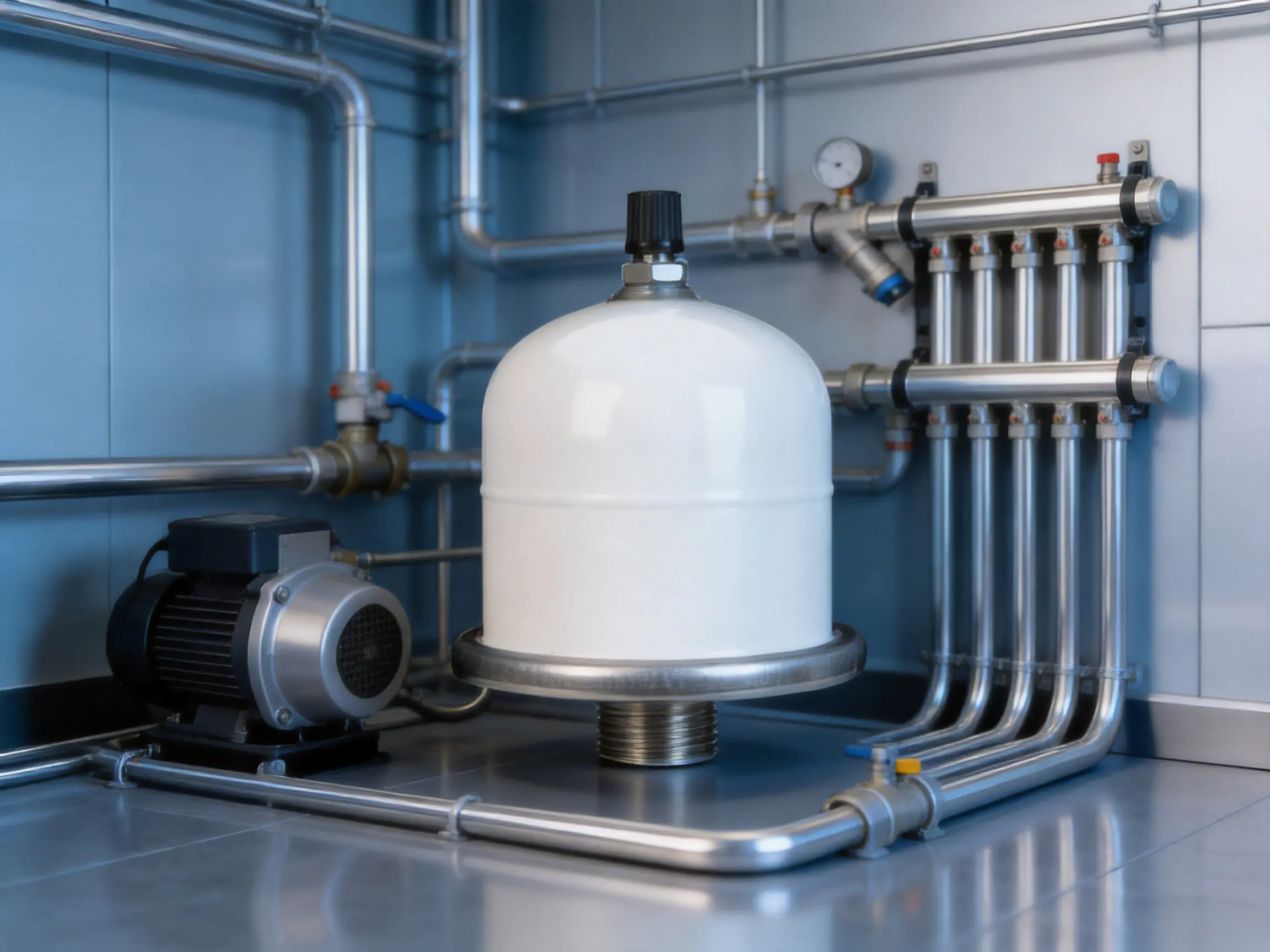
Heating circuits are a primary application for fixed membrane expansion tanks. When water is heated in a boiler, heat pump, solar thermal circuit, or hydronic system, its volume increases. The tank provides the additional space needed for that expansion and helps prevent excessive pressure growth.
The VT0.16 Series can be considered for compact heating systems where the required expansion volume is within the tank’s capacity. It may support boilers, circulation assemblies, heat exchangers, and packaged heating equipment. The design engineer must calculate the system water volume, temperature range, static height, and expansion coefficient to determine whether the selected tank is large enough.
In domestic booster systems, a pressure tank can reduce pump cycling during small or intermittent water demands. For example, a brief tap opening or minor leakage event may be handled partly by the stored tank volume, allowing the pump to remain off for longer periods. This can improve user comfort and reduce wear on the motor and control equipment.
The tank may be paired with surface pumps, intelligent booster pumps, or compact pressure sets. The controller and pressure switch should be configured so that the pump does not operate beyond the tank’s pressure rating. For potable-water use, the purchaser should verify that the membrane, internal surfaces, coatings, and manufacturing process comply with the applicable national requirements.
Heating, ventilation, and air-conditioning systems often contain closed water circuits that experience temperature variation. A compact expansion tank can help stabilize pressure in circulation loops and reduce the risk of relief-valve discharge during normal thermal changes.
The product may be suitable for selected HVAC assemblies, fan-coil systems, radiant heating circuits, and small chilled-water installations, provided the fluid temperature and chemical composition remain within the approved range. Glycol mixtures and treatment chemicals should be reviewed carefully because they may affect membrane materials and seals.
Commercial buildings, workshops, agricultural facilities, and light industrial plants frequently use packaged water systems that need controlled pressure in a limited space. The VT0.16 Series can be evaluated for these applications as an auxiliary tank in a larger pump or heating package.
Industrial use requires a detailed review of process conditions. The tank should not be selected solely because its nominal pressure and temperature appear suitable. Engineers should consider fluid density, chemical compatibility, cyclic frequency, ambient corrosion, vibration, mounting, and the consequences of vessel failure. Where local pressure-vessel regulations apply, the complete approval and documentation package must be obtained before use.
The tank should be installed by qualified personnel familiar with pressurized water systems. Before installation, inspect the vessel, flange, connection, membrane-related components, and packaging for damage. Do not install a tank that has been dropped, dented, heavily scratched, or otherwise compromised.
Confirm the operating pressure, temperature, connection size, installation orientation, and system volume. The tank should be connected at a point where pressure changes can be effectively transmitted and where service access is available. In many applications, the connection is placed near the pump discharge or within the heating circuit according to the system design.
Use a suitable isolation valve where permitted by the system design. An isolation arrangement allows the tank to be inspected or replaced without draining the complete installation. If an isolation valve is fitted, it must not be left closed while the system is operating unless the isolated section has an independent and appropriate safety arrangement.
Check the precharge before the tank is placed into service. The water side should be isolated and depressurized before measuring precharge, because a pressure reading taken while the tank is connected to a pressurized system may be misleading. Use calibrated instruments and follow the manufacturer’s instructions for adjustment.
Install a pressure relief valve and other required safety devices independently of the expansion tank. The tank is not a substitute for overpressure protection. The relief valve should be selected and set according to the system design and the rating of the lowest-rated connected component.
Support the pipework properly and avoid placing excessive mechanical load on the tank connection. Vibration from pumps should be controlled through suitable piping design, flexible connectors, alignment, and equipment supports. Thread sealants and joining materials should be compatible with the connection and the system fluid.
Routine maintenance begins with visual inspection. Look for corrosion, leakage, damaged threads, unusual deformation, coating failure, loose supports, and signs that the relief valve has discharged. A small leak should not be ignored because repeated pressure loss may indicate incorrect precharge, a damaged membrane, a faulty valve, or a problem elsewhere in the system.
Check system pressure during normal operation and compare it with the design values. Sudden changes may indicate loss of gas charge, pump-control problems, blocked pipework, excessive thermal expansion, or a leaking safety valve. Pressure readings should be interpreted alongside temperature and operating conditions.
Precharge should be verified at appropriate service intervals and whenever the system behaves abnormally. Before testing, isolate and depressurize the water side safely. If the measured pressure is lower than expected, use only an approved charging method and gas. Do not exceed the tank’s permitted pressure.
Membrane tanks can experience fatigue over time, particularly in systems with frequent cycling, high temperature, or incorrect pressure settings. If the tank repeatedly loses precharge, produces unusual noise, or allows pressure to fluctuate excessively, it should be removed from service for professional assessment.
Maintenance intervals depend on application, local regulations, duty cycle, water quality, and manufacturer guidance. Commercial and industrial users should maintain inspection records that include pressure readings, dates, observed conditions, and corrective actions.
Correct sizing is essential to obtaining the expected performance. The designer should calculate the total water volume in the circuit, the minimum and maximum operating temperatures, the static pressure, the desired pressure range, the pump control settings, and the available installation space.
For a heating system, the tank must accommodate the water expansion between the minimum filling temperature and the maximum operating temperature. The volume of boilers, radiators, pipes, heat exchangers, and other components should be included. A tank that is too small may cause frequent relief-valve operation and unstable pressure.
For a booster system, the tank should be matched to the pump flow, pressure-switch settings, expected demand pattern, and acceptable number of starts per hour. A larger tank generally provides more drawdown, but it may require more space and a higher initial investment. The best result is achieved by balancing capacity, pressure range, efficiency, and lifecycle cost.
Precharge must be coordinated with the application. If it is too high, the tank may accept too little water and provide limited buffering. If it is too low, the membrane may travel excessively or the available pressure support may be inadequate. The supplied 3.5 bar value is a reference for the listed configuration, not a universal setting for every system.
A pressure tank is often purchased as an individual accessory, but its performance is connected to the pump and control system around it. A manufacturer with experience in deep well pumps, submersible pumps, booster pumps, circulation pumps, solar pumping, and intelligent water systems understands the practical conditions in which tanks operate.
This broader experience can improve technical communication during project planning. A buyer can discuss pump cycling, pressure stability, tank selection, system packaging, and accessory compatibility with a supplier that understands the full hydraulic application. It can also simplify sourcing when the customer needs pumps, tanks, valves, pipes, and control components from a coordinated supply chain.
Taizhou Edwin Electric Co., Ltd. emphasizes independent development, mass production, international supply, and one-stop procurement support. Its products are used in areas including agricultural irrigation, municipal engineering, mining, construction, HVAC, household water supply, and new-energy projects. This market exposure provides a practical foundation for designing products that must function reliably in varied operating environments.
The company’s development of solar water pumps and intelligent booster pumps reflects a focus on energy efficiency and smart control. In a modern pump system, reducing energy use depends not only on motor efficiency but also on avoiding unnecessary starts, controlling pressure accurately, and selecting appropriately sized hydraulic accessories. A correctly applied expansion tank can support these goals by storing a limited volume of pressurized water and smoothing system demand.
Before placing an order, buyers should confirm the exact model designation, tank volume, shell material, flange material, membrane material, maximum pressure, temperature range, precharge, connector type, dimensions, and package quantity. The VT0.16-XY data should be checked against the latest technical drawing because the supplied dimensional table is abbreviated.
Application information should include the fluid type, expected temperature, normal pressure, maximum pressure, static head, pump model, system volume, installation orientation, and intended market. These details help the factory determine whether the standard model is suitable or whether a different configuration is required.
For export projects, customers should also request product labels, inspection records, packaging details, country-specific compliance documentation, and any required declarations. If the tank will be used with potable water, chemical fluids, or regulated pressure equipment, the buyer should identify those requirements before production begins.
For larger orders, it is useful to confirm sample approval, production lead time, batch traceability, spare-part policy, warranty terms, and after-sales communication procedures. A clear technical specification reduces the risk of misunderstanding and allows both the purchaser and manufacturer to evaluate performance against the same criteria.
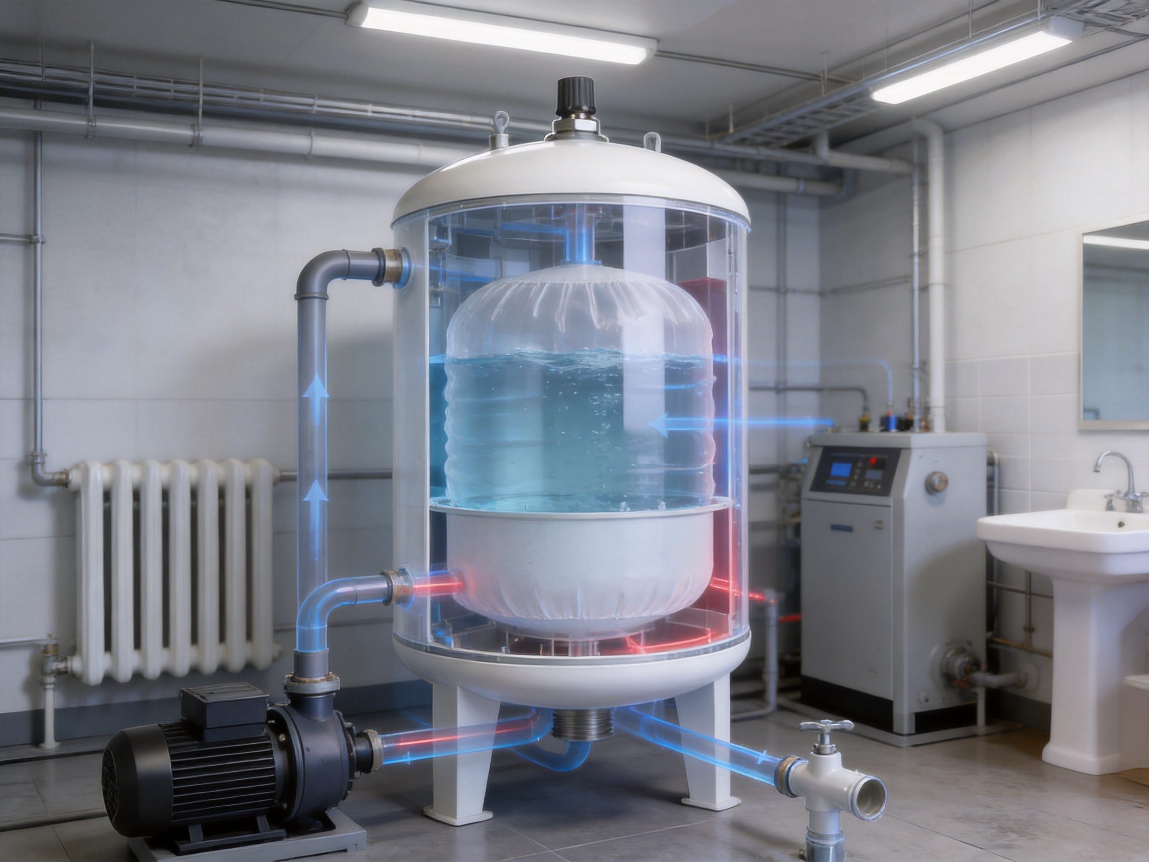
Its primary purpose is to absorb water expansion and pressure fluctuations in heating systems, water supply networks, booster systems, and other compatible pressurized applications. It provides a controlled water volume separated from a compressed gas chamber by a fixed membrane.
The 8 bar rating identifies the maximum stated pressure for the listed configuration. It is not necessarily the normal operating pressure. The actual system must be designed below this limit and must include appropriate safety protection.
Yes. The product information specifically identifies the tank for heating systems and states a working temperature range of -20°C to +99°C. The installer must calculate the required expansion volume and confirm that the selected size is suitable for the complete heating circuit.
A fixed membrane separates water from the gas charge and provides a compact integrated pressure-buffering arrangement. It can reduce the number of removable internal components and support consistent factory assembly. Correct sizing and periodic inspection are still required.
No. The listed 3.5 bar precharge applies to the supplied configuration as a reference value. The correct setting depends on static pressure, pump controls, system temperature, desired drawdown, and the application. It should be checked and adjusted by qualified personnel.
The supplied technical data identifies a 1/2-inch connector. Buyers should confirm the thread standard, connector material, and final drawing before installation because regional connection specifications may differ.
Potentially, but the purchaser must confirm that the complete tank configuration, including membrane, internal surfaces, materials, and production process, complies with the applicable potable-water requirements in the destination market. The nominal pressure and temperature ratings alone do not establish potable-water approval.
No. The expansion tank helps manage normal pressure changes, but it does not replace an independently selected and correctly installed pressure relief valve or other required safety equipment.
It stores a limited volume of pressurized water, allowing some small demands to be met without immediately starting the pump. This can reduce short cycling, motor starts, noise, and wear when the tank is correctly sized and adjusted.
Maintenance generally includes visual inspection, leak checks, pressure monitoring, precharge verification, and examination of the connection and support arrangement. The water side must be isolated and depressurized before precharge is measured.
Provide the intended application, fluid, temperature range, normal and maximum pressure, system volume, pump details, required connector, installation orientation, destination market, quantity, and any certification or packaging requirements. This information enables a more accurate technical and commercial response.
The VT0.16 Series Stainless Steel Flange 8 Bar Fixed Membrane Expansion Pressure Tank is a compact pressure-management solution for compatible heating, water supply, booster, circulation, and light commercial applications. Its principal strengths include fixed membrane technology, an 8 bar maximum pressure rating, a -20°C to +99°C working temperature range, a compact connection, and stainless steel flange construction.
Compared with basic open vessels or unprotected conventional pressure buffers, the tank can provide cleaner separation between water and gas, improved pressure stability, reduced pump cycling, and better resistance to corrosion when correctly matched to the application. These benefits depend on proper sizing, precharge adjustment, installation, safety protection, and maintenance.
The manufacturer’s integrated capabilities in research and development, mass production, pump manufacturing, intelligent water technology, and global export provide a strong foundation for supplying the tank as part of a complete water-system solution. Customers can benefit from coordinated procurement and technical communication across pumps, pressure accessories, and related equipment.
Before purchase or installation, users should verify the final technical drawing, tank capacity, dimensions, material details, membrane compatibility, regulatory documentation, and application-specific operating limits. With these checks completed, the VT0.16 Series can serve as a dependable component for improving pressure control, protecting connected equipment, and supporting efficient operation in modern water and heating systems.
1. Product specification supplied for the VT0.16 Series Stainless Steel Flange 8 Bar Fixed Membrane Expansion Pressure Tank.
2. Manufacturer information supplied for Taizhou Edwin Electric Co., Ltd., including company history, product portfolio, manufacturing capabilities, and export services.
3. General engineering principles for diaphragm and membrane expansion vessels used in closed heating and water-supply systems.
4. General guidance on pressure-vessel selection, precharge adjustment, hydraulic expansion, pump cycling, and system safety protection.
5. General installation and maintenance practices for pressurized water systems, hydronic heating circuits, and booster-pump assemblies.

edwina@edwin-pump.com
+86-13586290903 (WhatsApp)
Xuri Gongliang Cutting Tool Entrepreneurship Park, Wenqiao Town, Wenling City, Taizhou City, Zhejiang Province, China

High Performance Smart Pump Factory


 English